Install custom robot kinematics
Flowstate can be used to control a robot with custom kinematics and visuals. This is an expert task and not recommended for beginners.
Installing robot kinematics is an experimental and advanced feature that may require deployment restarts and manual configuration adjustments.
This guide assumes that the robot is already set up for usage with Flowstate according to the guide for the respective robot family.
Start by modifying the example robot model and follow the guide for using preconfigured resources.
Custom robot model
Modify one of the example robots to match your requirements.
- Kuka KR6 inspired model (download KR6 example)
- Joint devices
- Digital IO (DIO) devices
spherical_wristinverse kinematics solver
- UR20 inspired model (download UR20 example)
- Joint devices
- DIO devices
- f/t sensor
urinverse kinematics solver
Helpful links for creating a robot model
- SDF Format (external)
- Tutorial on building a model (external)
- Guide for adding and optimising geometry
File layout and <uri>
We recommend a flat (no subfolders) zip file that includes the sdf file and geometry files. This way no paths need to be specified for referencing the geometry files.
Example zip layout:
├── base.dae
├── ...
└── robot.sdf
Example reference in the sdf:
<uri>model://base.dae</uri>
Custom sdf tags
Intrinsic uses custom sdf tags to model Flowstate specific settings for controlling robots that are not covered by the sdf standard.
<intrinsic:ik_solver>
The custom tag <intrinsic:ik_solver> defines the inverse kinematics (IK) solver used by the realtime control service.
Most robots should use spherical_wrist. For UniversalRobots use ur.
Example:
<model name='robot'>
   ...
   <intrinsic:ik_solver>spherical_wrist</intrinsic:ik_solver>
   ...
If no valid solver is configured, posing using the frontend won't work, and Cartesian jogging and admittance control will not be available.
<intrinsic:cartesian_limits>
Optional tag to define Cartesian limits. It is recommended to set at least acceleration and velocity limits. Unset limits default to infinty.
Uses SI units e.g. position in m, rotation in rad.
Example:
<model name='robot'>
   ...
   <intrinsic:cartesian_limits>
      <intrinsic:min_translational_position>-5 -5 -5</intrinsic:min_translational_position>
      <intrinsic:max_translational_position>5 5 5</intrinsic:max_translational_position>
      <intrinsic:min_translational_velocity>-0.2 -0.2 -0.2</intrinsic:min_translational_velocity>
      <intrinsic:max_translational_velocity>0.2 0.2 0.2</intrinsic:max_translational_velocity>
      <intrinsic:min_translational_acceleration>-5 -5 -5</intrinsic:min_translational_acceleration>
      <intrinsic:max_translational_acceleration>5 5 5</intrinsic:max_translational_acceleration>
      <intrinsic:min_translational_jerk>-10 -10 -10</intrinsic:min_translational_jerk>
      <intrinsic:max_translational_jerk>10 10 10</intrinsic:max_translational_jerk>
      <intrinsic:max_rotational_velocity>0.3</intrinsic:max_rotational_velocity>
      <intrinsic:max_rotational_acceleration>5</intrinsic:max_rotational_acceleration>
      <intrinsic:max_rotational_jerk>10</intrinsic:max_rotational_jerk>
   </intrinsic:cartesian_limits>
   ...
<intrinsic:acceleration> and <intrinsic:jerk>
Extends the <limit> tag of every joint axis with acceleration and jerk limits in rad/s² and rad/s³ respectively.
The limits in the sdf are used to automatically create application limits with some leeway for control.
Those application limits can later be adjusted through Flowstate.
Example:
<model name='robot'>
   ...
    <joint name="joint_..." type="revolute">
      ...
      <axis>
        ...
        <limit>
          <effort>342</effort>
          <lower>-3.1</lower>
          <upper>3.1</upper>
          <velocity>6.2</velocity>
          <intrinsic:acceleration>20.123</intrinsic:acceleration>
          <intrinsic:jerk>4242.42</intrinsic:jerk>
        </limit>
   ...
Flange frame
The flange is used for attaching endeffectors to the robot and as the tip of the kinematic chain.
It is added as a frame using the special name flange using the tag intrinsic:create_attachment_entity='true'.
Example of adding a flange attached to a link named name_of_final_link:
<model name='robot'>
   ...
   <frame name='flange' attached_to='name_of_final_link' intrinsic:create_attachment_entity='true'/>
</model>
Simulation
SDF models need some additional configuration to support simulation in the Intrinsic platform.
Basic functionality works out of the box without extra configuration:
- Rotary and prismatic
<joint>tags - Force/Torque sensors using Gazebo's
<sensor>tag andForceTorque/SensorsSystems
Digital and analog IO devices require extra configuration.
The Intrinsic platform automatically marks any assets that belong to a robot hardware module (HWM) for simulation and auto-detects joints and sensors, no further action needed.
Drives
Regular SDF <joint> tags work out-of-the-box, as long as the joints are either rotary or prismatic.
For accurate simulation, please double-check that your model has
- realistic effort limits
- correct inertial parameters (see this detailed Gazebo documentation page for information on what the inertial parameters are and how to determine/estimate them.
ForceTorque Sensor
To add a simulated force/torque sensor to your model, simply add a <sensor> tag to any of the model's joints. You can use the <force_torque> tag below <sensor> to set noise parameters.
<joint name='wrist_3_joint' type='revolute'>
    <pose relative_to='wrist_2_link'>0 0.1542999999 0 -1.57079632679 3.14159265359 0</pose>
    <parent>wrist_2_link</parent>
    <child>wrist_3_link</child>
    <!-- Putting this on a fixed joint would be more accurate, but also more invasive to the model. -->
    <sensor name="InternalForceTorqueSensor" type="force_torque">
        <topic>/internal/wrench</topic>
        <always_on>true</always_on>
        <visualize>true</visualize>
        <force_torque>
            <frame>child</frame>
            <force>
                <x>
                    <noise type="gaussian">
                        <mean>0.0</mean>
                        <stddev>0.2</stddev>
                    </noise>
                </x>
                <y>
                    <noise type="gaussian">
                        <mean>0.0</mean>
                        <stddev>0.2</stddev>
                    </noise>
                </y>
                <z>
                    <noise type="gaussian">
                        <mean>0.0</mean>
                        <stddev>0.2</stddev>
                    </noise>
                </z>
            </force>
            <torque>
                <x>
                    <noise type="gaussian">
                        <mean>0.0</mean>
                        <stddev>0.05</stddev>
                    </noise>
                </x>
                <y>
                    <noise type="gaussian">
                        <mean>0.0</mean>
                        <stddev>0.05</stddev>
                    </noise>
                </y>
                <z>
                    <noise type="gaussian">
                        <mean>0.0</mean>
                        <stddev>0.05</stddev>
                    </noise>
                </z>
            </torque>
        </force_torque>
    </sensor>
</joint>
Analog and Digital I/O devices
Digital I/O devices need special configuration, because there is no native SDF tag to represent them.
In addition, you may choose to manually configure digital I/O devices further in the HWM configuration for your robot, but the default behavior will be correct in most cases.
You can see an example of an SDF configuration snippet and the resulting Realtime Control Service configuration.
SDF
To simulate a bank of digital inputs and outputs
- Add a
DigitalInputOutputplugin to your model's SDF file - Add one or more
<input>/<output>tags to that plugin
If your robot has any analog input devices, please add those to the HWM configuration file. The Intrinsic platform does not simulate analog I/O behavior, but allows you to create "dummy" interfaces so that your simulated robot works with the same Realtime Control Service configuration that the real one uses.
Each <input> and <output> should correspond to one of the digital input/output hardware interfaces on the real robot. That is, they should have the same names and number of bits.
<plugin filename="static://intrinsic::simulation::DigitalInputOutput" name="DigitalInputOutput">
  <input_block name="standard_digital_input_status"
               num_bits="8" />
  <input_block name="standard_digital_output_status"
               num_bits="8" />
  <output_block name="standard_digital_output_command"
                num_bits="8" />
  <input_block name="configurable_digital_input_status"
               num_bits="8" />
  <input_block name="configurable_digital_output_status"
               num_bits="8" />
  <output_block name="configurable_digital_output_command"
                num_bits="8" />
  <input_block name="tool_digital_input_status"
               num_bits="2" />
  <input_block name="tool_digital_output_status"
               num_bits="2" />
  <output_block name="tool_digital_output_command"
                num_bits="2" />
</plugin>
See Digital IO configuration for more information.
HalADIOPartConfig
In the configuration for your Realtime Control Service, add a part that uses HalADIOPartConfig.
As mentioned above, the simulated robot hardware module uses the names in the <input> and <output> tags for its hardware interfaces (interface_name).
Note that this configuration also defines an export_name for each input/output. This is optional, but if present, it defines the name that the real-time control service uses for each input/output (and consequently, the name that skills must use if they want to send commands to the real-time control service):
[type.googleapis.com/intrinsic_proto.icon.HalADIOPartConfig] {
analog_inputs: [
   { interface: { module_name: "ur_module" interface_name: "analog_input_status" } }
]
digital_inputs: [
   { interface: { module_name: "ur_module" interface_name: "standard_digital_output_status" } export_name: "standard_out_status" },
   { interface: { module_name: "ur_module" interface_name: "configurable_digital_output_status" } export_name: "configurable_out_status" },
   { interface: { module_name: "ur_module" interface_name: "tool_digital_output_status" } export_name: "tool_out_status" },
   { interface: { module_name: "ur_module" interface_name: "standard_digital_input_status" } export_name: "standard_in" },
   { interface: { module_name: "ur_module" interface_name: "configurable_digital_input_status" } export_name: "configurable_in" },
   { interface: { module_name: "ur_module" interface_name: "tool_digital_input_status" } export_name: "tool_in_status" }
]
digital_outputs: [
   { interface: { module_name: "ur_module" interface_name: "standard_digital_output_command" } export_name: "standard_out" },
   { interface: { module_name: "ur_module" interface_name: "configurable_digital_output_command" } export_name: "configurable_out" },
   { interface: { module_name: "ur_module" interface_name: "tool_digital_output_command" } export_name: "tool_out" }
]
}
Module Configuration
  simulation_module_config {
    ...
    # Add an analog input device – the UR HWM adds one, but we don't simulate those.
    additional_devices: {
      name: "analog_input"
      analog_input: {
        num_inputs: 2
      }
    }
  }
Using preconfigured resources (recommended)
This guide uses assets that are preconfigured to load kinematics and settings from a SceneObject called robot.
The preconfigured assets expect the following names:
- Robot geometry:
robot - Hardware Module:
hardware_module - Realtime Control Service:
robot_controller
Using different names invalidates the configuration for the realtime control service and the simulation configuration of the hardware module. Follow these instructions to adjust the configurations.
-
Upload your custom robot model with name
robotfollowing the guide to upload a Scene Object. -
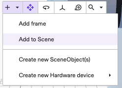
Add a
realtime control servicethat is preconfigured for your robot family using the default name ofrobot_controller.- Open the Add Asset dialog as shown in the picture.
- Check if there is a
realtime control servicefor your robot family with a name ending infor_sideloaded_geometry.
If not, add the generic one for your robot family.
- Open the Add Asset dialog as shown in the picture.
-
Add the correct hardware module for your robot family using the default name of
hardware_module.- Open the Add Asset dialog.
- Filter Family for
Hardware_module_without_geometry.

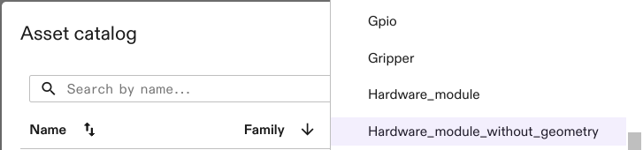
Tip: The name of the modules end in_without_geometry.
-
Refresh/reload your browser tab. Otherwise the Cartesian jogging controls won't be visible.
(Optional) Using custom names (expert)
In case the hardware module, or the robot geometry uses a different name than the preconfigured resources, the default configuration for the realtime control service and the simulation configuration of the hardware module are no longer valid.
Hardware module
To change the configuration, select the hardware module asset from the services view, click Settings and from there Manage configuration.
This will display the configuration of the asset.
-
In the
simulation_module_configreplacegeometry_asset_namewith the name of the robot geometry.simulation_module_config {
new_sim_api_config {
geometry_asset_name: "robot"
...
}
} -
When using an EtherCAT module (e.g. for a f/t sensor), check that its
cycle_time_usecmatches the Realtime control service and the control frequency for your robot model.
Realtime control service
To change the configuration, select the realtime control service asset from the services view, click Settings and from there Manage configuration.
This will display the configuration of the asset.
In there,
- change the values of
hardware_resource_nameandworld_robot_collection_name(HalForceTorqueSensorPart) to the name of the robot geometry. - change all occurences of
module_name:, the relevant entry inhardware_module_namesand potentiallyhardware_module_that_drives_clockto the name of the hardware module resource. If the module defines a customname: "custom_module_name", use this name. - Check the value of
control_frequency_hz:. It defines the realtime cycle frequency in Hertz for controlling the robot and must match the value in the robot hardware module configuration.
Troubleshooting
Toast: Failed to add resource type when adding hardware_module
The message toast containing Could not clear ICON faults within 30s of simulation when adding a hardware_module can simply be Dismissed.
Example message:
Failed to add resource type ai.intrinsic.kuka_rsi_hardware_module_without_geometry.0.0.1+intrinsic.platform.20240619.RC01 as hardware_module: failed to create(commit) resource: "hardware_module": failed to update world with "hardware_module": rpc error: code = Internal desc = could not update world with local world id "world" with error: ResetSimulation: rpc error: code = DeadlineExceeded desc = Could not clear ICON faults within 30s of simulation reset, aborting. ... ;
Control panel shows Realtime Control Service is missing
If the control panel shows
Realtime Control Service is missing, restarting or offline. Did you add a 'realtime_control_service' asset?
but the realtime control service is already added, there are two possibilities:
-
Without added hardware_module:
Continue adding thehardware_module. -
With added hardware_module:
- Check the names in the configuration of the realtime control service and hardware module.
- File | Save then File | Redeploy.
- Potentially press Clear faults.