Create a SceneObject
You can build a workcell step-by-step, creating and placing SceneObjects individually. Alternatively, upload a collection of objects as an editable scene with the Scene Object Import Dialog. Both workflows can be invoked via the toolbar at the top of the 3D Scene editor.
You need a running Solution before adding an object; please start or create a Solution first.
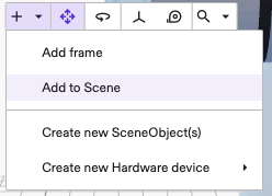
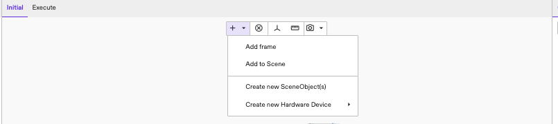
From the Flowstate Editor, you can upload files from your local computer to create SceneObjects. To upload from a file, click the + icon in the top toolbar and select Create SceneObject(s) from the drop-down menu.
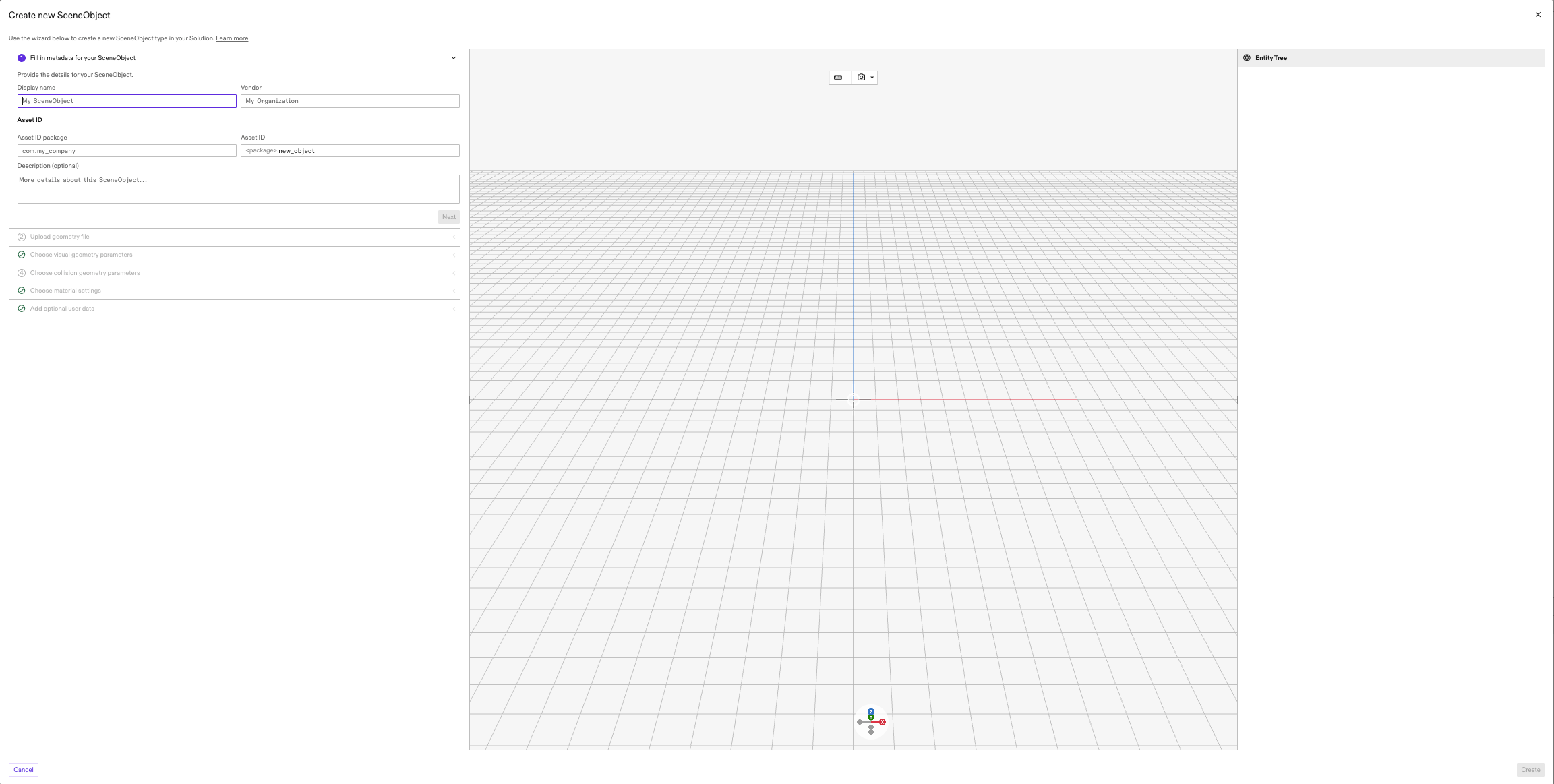
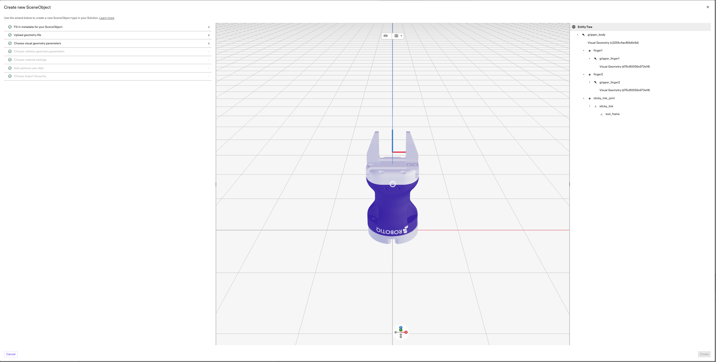
An import dialog appears with three panels, arranged from left to right: the Scene Object Form, the Preview Scene, and the Entity Tree. The user can modify the SceneObject being imported via the Scene Object Form and the generated SceneObject(s) are rendered in the Preview Scene where the entity tree structure of the SceneObject(s) are shown in the Entity Tree.
Completing the Scene Object Form
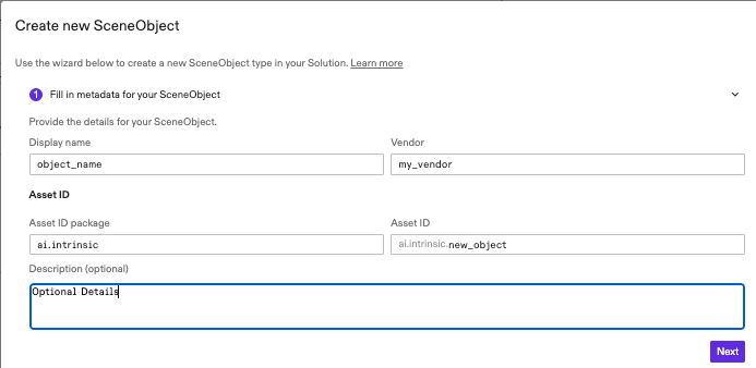
1. Fill in metadata for your SceneObject Asset
The import dialog will first prompt you to define the metatdata of the SceneObject Asset.
- Display Name: The name that will be searchable once the SceneObject Asset is imported.
- Vendor: The organization that owns the asset being imported.
- Asset ID Package: A unique identifier for the asset.
We recommend that your asset id package follow the reverse DNS notation,
for example, if your domain is my_company.com you should use com.my_company
note
Filling this field will automatically generate a default prefix for the Asset ID, but you can edit the ID.
- Optional Description: A brief, optional text description of the object.
2. Upload Geometry File
Flowstate supports the following file formats:
- .stl/.glb/.obj for geometry meshes as SceneObjects
- .pts for point clouds as SceneObjects
- .step/.stp for STEP files as scenes (commonly used by CAD programs)
- .zip for compressed
Gazebo SDF
files as scenes with corresponding geometry files in a ZIP archive. Try
uploading different types of Scenes / SceneObjects with the following
example SDF files:
- Static SDF.
- Single Kinematic Object (Robot) SDF.
- Single Kinematic Object (robot) USD/USDA/USDC/USDZ
- SDF with multiple kinematic models (Coming soon)
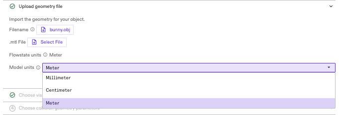
To upload one of the supported file formats, click the Select File button to select a file containing the geometries to be imported.

If this file is a .obj file, a .mtl file can also be uploaded to specify the
visual appearance.

The unit of distance in a Flowstate Solution is meters. Convert all input geometry coordinates to meters before adding them to Flowstate.
You can set the unit of distance for the single scene object files -
.stl/.glb/.obj/.pts - by selecting from the drop-down.
Input geometries are automatically converted into meters. Since STEP files always contain the native units of the original model, users need not specify units when importing. For SDF zip files, the constituent geometry files must be in meters and Flowstate does not perform any unit conversion on import.
After intial upload, the scene will display the visual mesh(es) and the Entity Tree will display the scene objects hierarchy.
Importing SDF
Current Limitations
- SDF should only contain a single
model. Nested models are not supported at this time. - SDF should not contain a
worldtag.
Inertial Attributes
For non-static objects, physically plausible inertial properties such as mass, center of mass, and moment of inertia matrix play an important role in achieving accurate physics simulation which leads to more natural movement of objects.
When importing objects into Flowstate, users are recommended to set at least the
<mass> property of each link in the model SDF. If the moment of inertia matrix
is also known (e.g. from a CAD tool), it is recommended to set those too. If
these values are not available, users can leave the field unspecified in SDF and
Flowstate will automatically compute the inertial values based on the collision
geometries in the link and the specified mass. In the case that mass is not
specified, the inertial values will be calculated by assuming the collision
geometries have a solid uniform density of water (1000 kg/m^3). If you do not
specify <inertial> for a link or any <collision> elements, the link is
assigned a default, minimal mass and moment of inertia.
Custom attributes
SDF import pipeline supports custom attributes to include information beyond the standard SDFormat specification. By default, the pipeline disregards implicit frames defined within the SDF.
intrinsic:create_entitycan be used to create a Frame:
<?xml version="1.0" encoding="UTF-8"?>
<!--
  Note: xmlns:intrinsic="https://intrinsic.ai" is required for the custom
  attribute listed in the <frame> tag below.
-->
<sdf version="1.11" xmlns:intrinsic="https://intrinsic.ai/">

  <model name="some_model_name">

  <!-- Provide model description like links here ... -->

  <!-- Create an explicit frame within a model --->
  <frame name="tool_frame"
           attached_to="base_link"
           intrinsic:create_entity="true">
        <pose>0 0 0 0 3.141592654 0</pose>
    </frame>

  </model>
</sdf>
intrinsic:create_attachment_entitycan be used to create an Attachment Frame:
<?xml version="1.0" encoding="UTF-8"?>
<!--
  Note: xmlns:intrinsic="https://intrinsic.ai" is required for the custom
  attribute listed in the <frame> tag below.
-->
<sdf version="1.11" xmlns:intrinsic="https://intrinsic.ai/">

  <model name="some_model_name">

  <!-- Provide model description like links here ... -->

  <!-- Create an explicit attachment frame within a model -->
  <frame name="flange"
           attached_to="A6_link"
           intrinsic:create_attachment_entity="true">
  </frame>

  </model>
</sdf>
3. Choose visual geometry parameters
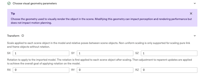
The Visual Mesh defines the object's geometric appearance in the scene for rendering.
You can apply a 3D transformation to the imported objects. For now, we only support uniform scaling and rotation. Rotation is specified in Euler angles in degrees.
You can select a Mesh refinement to process the geometry and view high-level statistics summarizing the processed meshes. The resulting visual mesh is displayed in the central scene
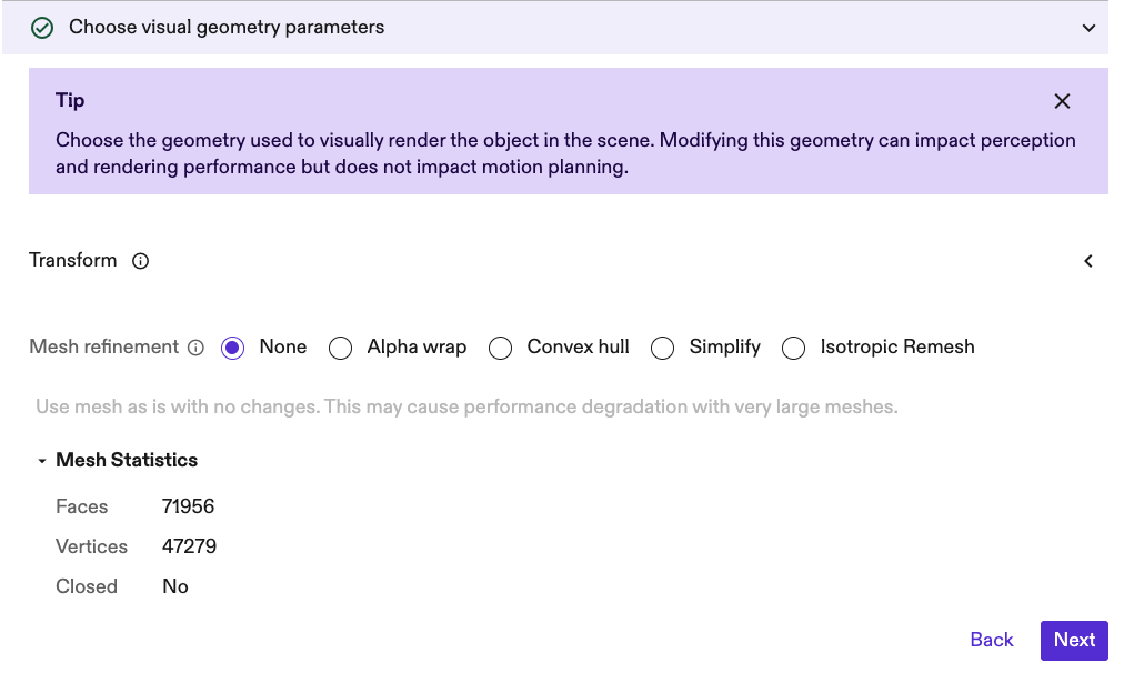
- None (Default): The visual geometry is imported without modification.
- Alpha Wrap: Generates a watertight mesh, which may be useful if the original input geometry is poor quality.
- Convex Hull: Generates the convex hull for the visual mesh.
- Simplify: Removes edges from the mesh to reduce mesh complexity.
- Isotropic Remeshing Generates a new mesh where all edges have a target length. This can be used to reduce or increase mesh complexity.
Note for Visual Mesh
Typically, users do not modify the underlying visual mesh and use the None operation to maintain the object's initial geometry.
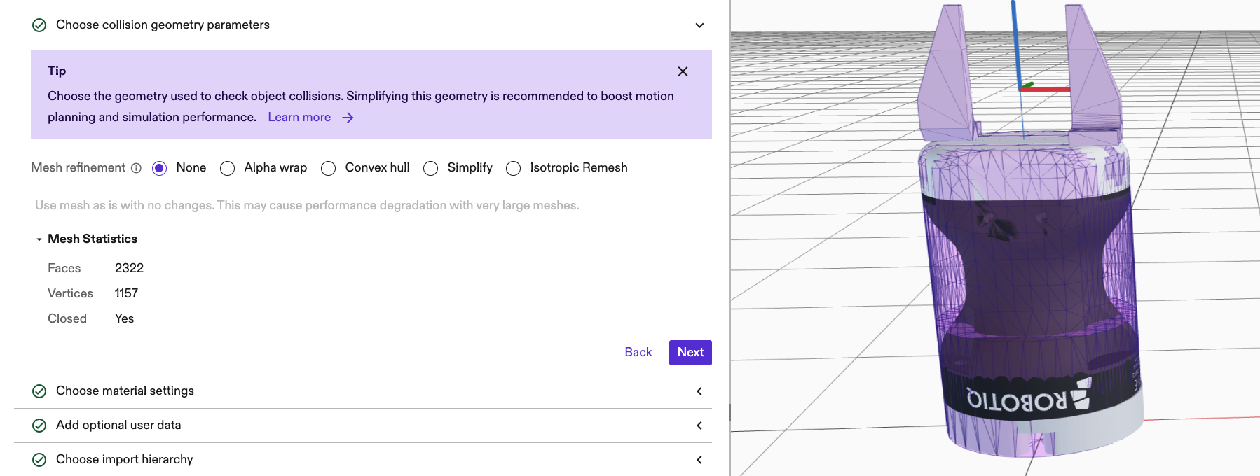
4. Choose collision geometry parameters
While importing a SceneObject you need to specify whether the imported object has a collision geometry. You can change the collision geometry later by editing the scene object as described here.
The Collision Mesh defines the geometry used for physics simulation, path planning, and interaction.
You can select the source geometry and apply a Mesh refinement to refine the mesh for the required application. The resulting collision mesh is displayed in the central scene as a purple overlay.
If a collision mesh is not already specified (like in a sdf). Source mesh can be selected.
-
Select Source Geometry:
- None (Default): The object will not contribute to collision computations.
- Use Visual Mesh: The object's visual geometry is used as the basis for
- collision calculations.
-
Select Mesh Operation:
- None (Default): No processing is applied to the selected source
- geometry.
- Alpha Wrap: Generates a watertight mesh, which may be useful if the
- original input geometry is poor quality.
- Convex Hull: Generates the convex hull for the source mesh
- Simplify: Removes edges from the mesh to reduce mesh complexity.
- Isotropic Remesh Generates a new mesh where all edges have a target length.
- This can be used to reduce or increase mesh complexity.
Note for Collision Mesh
Users typically try to reduce the complexity of the Collision Mesh to improve performance during simulation and path planning. The goal is commonly to minimize the number of faces and vertices using simplification operations like Convex Hull, Simplify, Alpha Wrap, and Isotropic Remesh.
Mesh refinement details
Mesh operations are available to modify the meshes to improve performance during path planning, simulation, and rendering.
1. Convex hull
Transforms the mesh into its convex hull, generating the smallest convex shape that completely encloses the original object. The resulting mesh is always watertight and is the simplest approach to implement as it has no control parameters.
- Primary Use: Simplifying meshes for collision detection and physics simulations where internal complexity is less relevant, often leading to excellent performance gains.
2. Alpha wrap
Generates a surface that "wraps" the original mesh, typically resulting in a smoother, simplified, and watertight representation. The tightness of the wrap is controlled by the Alpha Value.
- Default Value: 0.1
- Performance and Quality Considerations:
- Small Alpha: Closely wraps the mesh but is computationally expensive and slow.
- Large Alpha: Results in fewer triangles and faster computation, but the hull can be oversized and lose fidelity to small features.
Note for Selecting Alpha
Alpha is an absolute measure, so small and large values are only relevant in the context of the mesh and its size/features
3. Simplify
Removes edges from the mesh to reduce mesh complexity i.e. the number of edges and faces. The generated mesh will deviate by no more than the input Maximum Geometry Deviation (mm) from the inital mesh.
- Default Value: 1 mm
- Performance and Quality Considerations:
- Small Deviation: Result typically will have complexity similar to that of the original mesh, but it offers a closer approximation to the original mesh.
- Large Deviation: Result typically will have reduced complexity but may poorly approximate the original mesh.
Note for Selecting Maximum Geometric Deviation
The maximum geometric deviation is an absolute measure, so small and large values are only relevant in the context of the mesh and its size/features.
4. Isotropic Remesh
Generates a new mesh where all edges have a target length. The target edge length is controlled by the Edge Reduction Factor which scales the largest edge length of the mesh. The result is the target length.
- Default Value: 0.1
- Performance and Quality Considerations:
- Small Factor: Result typically will have high complexity similar to that of the original mesh, but it offers a closer approximation to the original mesh.
- Large Factor: Result typically will have reduced complexity but may poorly approximate the original mesh.
Note for Selecting Edge Reduction Factor
The Edge Reduction Factor is a relative measure so reasonable values are dependent on the length of the edges of the original mesh.
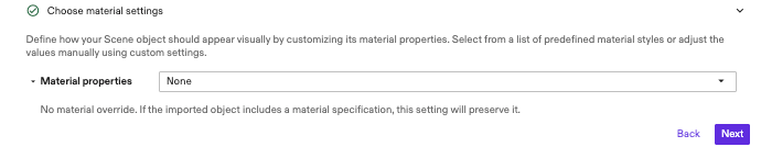
5. Material settings
Use the Material section of the import dialog to specify material attributes for the loaded object. When the selection is set to None, the material of the imported object, if any, will be preserved.
When one of the material presets or Custom option is selected from the drop-down menu, the material controls, and a sphere showing the preview of the material are shown.
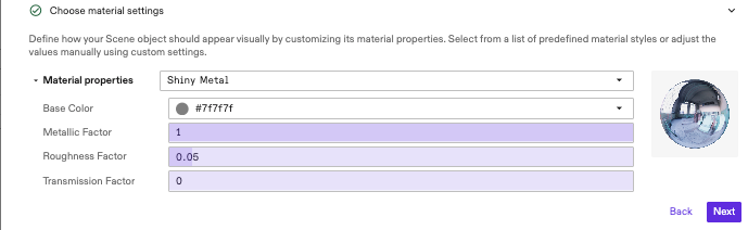
The preview is interactive and will mirror changes applied to color, metallic factor, roughness or transmission factor. Each of the following material styles controls a physical attribute of the material, which in turn directly affects the object's appearance:
- Base Color: Overall color of the material. Can be set using an interactive color picker.
- Metallic Factor: Controls reflectivity and how the material interacts with diffuse light.
- Roughness Factor: Controls the apparent roughness of the surface.
- Transmission Factor: Controls the translucency of the object.
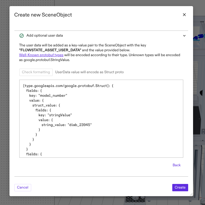
6. Add optional user data
Use the UserData section of the dialog to associate additional, custom data with the imported SceneObject. Data can be entered as either a text string or one of the Well-Known protobuf types. Click the Check formatting button to validate the data and view the selected encoding method.
Once the import process is completed, the userdata associated with an object can be viewed by selecting the object in the Scene editor, clicking the Scene tab in the properties panel and clicking the View object userdata button. A read-only dialog will open and display the userdata associated with the selected object.
7. Define import hierarchy structure
When a scene file containing multiple geometries is imported, you can specify what happens to the hierarchy in the input file. Two options are available:
-
Import as a single SceneObject (default): The import process merges all geometries in the file into a single object. This import option will maintain the input structure within the single scene object but the child geometries cannot be independently reparented to some other object.
-
Import as multiple SceneObjects: Flowstate attempts to respect the original scene structure by importing each node in the scene graph as a separate SceneObject. The user can further manipulate and edit the child scene objects independently.

8. Validate Kinematics
If the imported object contains non-fixed joints (prismatic and revolute), this optional section becomes available to help you verify the kinematics. A control panel will automatically appear, allowing you to jog the joints and visually validate their movement. Renderables will also display at each joint location to indicate the axes of motion.
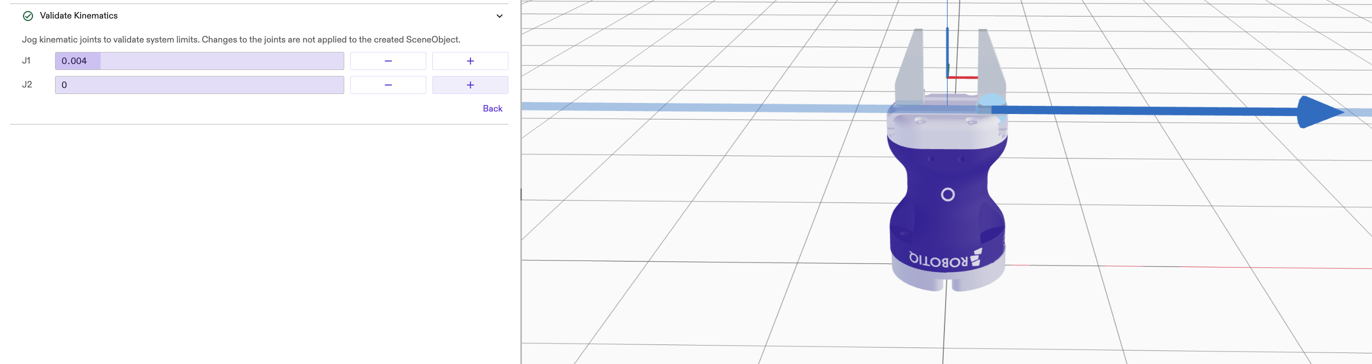
Note: Kinematic Validation
Joint editing is not currently supported. Any modifications to the joints must be made using third-party software.
Creation and Adding new instance dialog
After you click the Create button, a dialog appears asking to add an instance of the import object to the scene.
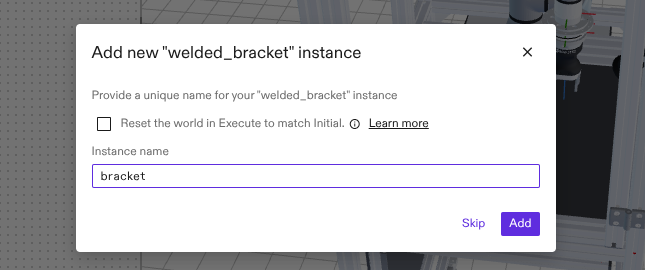 If a new
instance is created, the new object will appear in the scene with the name
specified in the Instance name field.
If a new
instance is created, the new object will appear in the scene with the name
specified in the Instance name field.
Import an object from catalog
The Asset Catalog contains all objects that were created or imported with the steps described previously. To enable users to import an object once and use it in multiple Solutions, Flowstate supports importing objects from the catalog to the workcell.
To import an object from the catalog, click the '+' button in the toolbar on the Scene editor. Select Add Asset from the drop-down. Use the search bar to find specific objects or filter for different types of objects (e.g. products and types of resources). Select the object that you want to import and click Add.