ENI generation with TwinCAT
As already mentioned on the EtherCAT Setup page, Flowstate currently requires an external tool, like TwinCAT 3, to generate an ENI file (EtherCAT Network Information) for its EtherCAT support. This page describes the steps required to obtain such a file from TwinCAT 3 for use with Flowstate's EtherCAT Hardware Module. You can find details on TwinCAT on the Beckhoff website.
Providing device-specific ESI files
EtherCAT device manufacturers typically provide ESI files (EtherCAT SubDevice Information) for most of their EtherCAT devices. These files describe the characteristics and capabilities of a device (or family of similar devices) and thus contain critical information for the EtherCAT MainDevice to enable a reliable communication. ESI files are usually available on the manufacturer website or can be obtained through a support request from the corresponding vendor.
If you have a device without an ESI file, you might still be able to use it based on the information this device publishes through its SII (SubDevice Information Interface). TwinCAT is able to query SII during a bus scan, so using such a device requires you to perform the online configuration, as described below.
TwinCAT expects ESI files to be available in a particular folder on your harddrive, which defaults to C:\TwinCAT\3.1\Config\Io\EtherCAT for TwinCAT 3. New ESI files need to be copied into this folder before TwinCAT is started.
Setup your project
Creating a new project
Once the ESI files are in place, open TwinCAT and click on File | New | Project... to open the corresponding dialog.
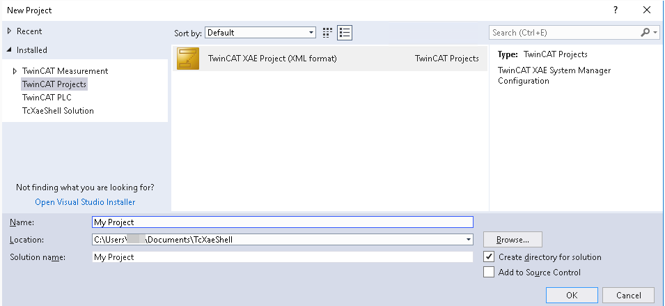
Select TwinCAT XAE Project (XML Format) and choose an appropriate Name and Location for the project. Confirm by selecting OK.
Online and offline configuration
With TwinCAT you have the choice to perform an online or an offline configuration:
-
Online configuration assumes that the EtherCAT bus devices are correctly wired and powered, such that TwinCAT can automatically perform a bus scan to identify the bus topology and (for some devices) even the terminal configuration. For this to work, you'll use TwinCAT as the MainDevice. In other words, your machine running TwinCAT needs to be connected to the input port of the first device on the bus. After the ENI export don't forget to disconnect your TwinCAT machine and instead connect the IPC EtherCAT port to first bus device.
-
With offline configuration, you manually create the bus topology and (if applicable) the terminal configuration of certain devices.
The following table should help you decide which configuration method to follow in your scenario.
| Criteria | Online configuration | Offline configuration |
|---|---|---|
| Physical connection | Requires the machine running TwinCAT to have a supported EtherCAT network device and be physically connected to the bus | Can be performed remotely, even with TwinCAT running in a virtual machine |
| ESI requirements | Compatible ESIs required for all bus devices | Compatible ESIs required for all bus devices |
| Bus topology | Topology and configuration are automatically derived | Topology and configuration need to be defined manually |
| Validation | Allows validating that bus devices are operational | Does not offer any validation |
If you can physically connect to the hardware, online configuration may be more convenient. Note that it does not warn about some wiring errors (i.e. wrong device order on the bus).
If you cannot fulfill the higher requirements, or if you want to ensure that your bus topology follows a previously specified design, you should follow offline configuration.
Defining the EtherCAT MainDevice
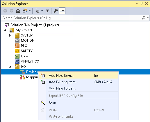
After your new project opened, find the Solution Explorer on the left side of the window, and expand the tree down to I/O | Devices. Select Add new Item... from the Devices context menu.
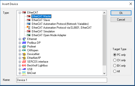
From the device list, select EtherCAT Master (old name for EtherCAT MainDevice) and confirm by selecting OK.
If your machine provides compatible network devices, a dialog with the title Device Found At will open up with a list of these devices. If you plan to perform the online configuration and scan the available devices on the bus, select one of the shown network devices and click OK. Select Cancel if you don't intent to follow online configuration.
If your machine doesn't provide a compatible network device, the dialog will be shown with an empty list. This means that you are limited to offline configuration and can proceed by selecting Cancel.
Online configuration
You can skip this step if you want to follow offline configuration.
Connect the EtherCAT cable to the network device of your TwinCAT machine, which you selected in the previous step.
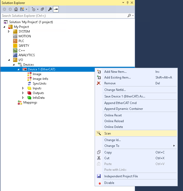
In the Solution Explorer, open the context menu of the EtherCAT MainDevice, usually called Device 1 (EtherCAT) and select Scan. Follow the dialog to automatically obtain the bus configuration. Consult the official TwinCAT documentation for further information or in case of issues.
Offline configuration
You can skip this step if you just followed online configuration.
For the offline configuration, you need to add bus devices one by one. We recommend adding devices according to their order as they appear on the actual bus. However, TwinCAT allows to adjust the order in a later step by drag-and-drop.
For each bus device, open the context menu of the EtherCAT MainDevice, usually called Device 1 (EtherCAT), and select Add New Item....
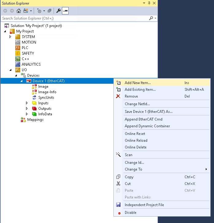
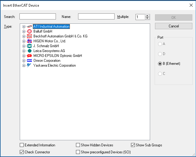
This opens a dialog window showing all known devices grouped by vendor. The vendors of your provided ESIs should be among them. We recommend using the Search box on the top to quickly find your devices.
Junctions
If you are using a junction, you need to fill out the Previous Port of a bus device connected to the junction. In the following image, the device Term 2 (ATI Axia F/T Sensor) was added right after Box 1 (GX-JC03) (the junction) and its Previous Port was set to Box 1 (GX-JC03) - B 'X3'. To change this port to X2 (the other available port of the junction), double click on the Term 2 (ATI Axia F/T Sensor) and select the EtherCAT tab in the center part of the screen. Then, select the other port from the Previous Port dropdown menu.
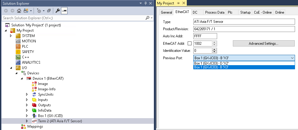
Once you changed the previous port to Box 1 (GX-JC03) - B 'X3' you will notice, that Term 2 (ATI Axia F/T Sensor) will be displayed slightly indented as a child of Box 1 (GX-JC03) in the Solution Explorer. You can achieve the same result by dragging Term 2 (ATI Axia F/T Sensor) onto Box 1 (GX-JC03) and selecting Insert As Child from the appearing menu.
Couplers and terminals
Some bus devices (i.e. bus couplers like the Beckhoff EK1100) are extensible though a variety of different terminals (i.e. with analog or digital inputs and outputs, such as the Beckhoff EL1008).
To add a terminal, select Add New Item... from the context menu of the bus coupler Term 2 (EK1100) as opposed to Device 1 (EtherCAT).
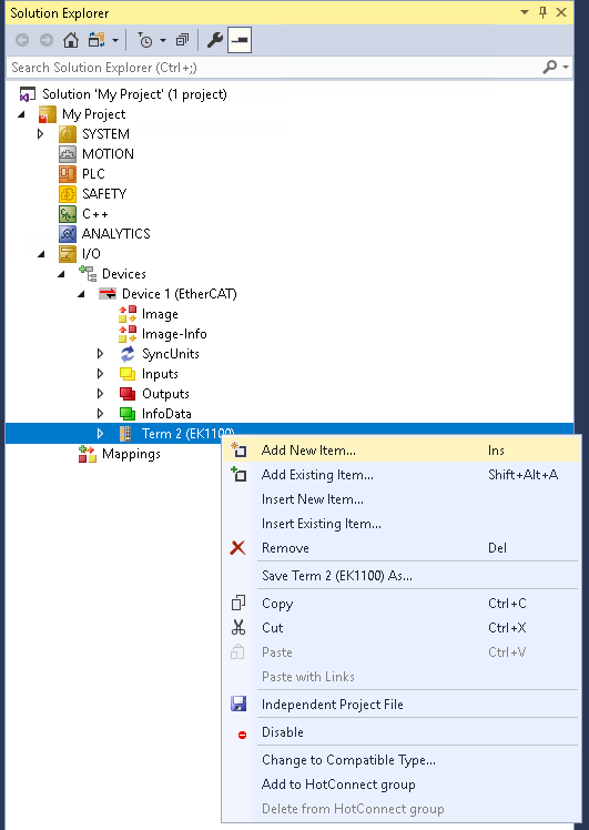
Then, similar to selecting a bus device, select the required terminal from the appearing dialog. Terminals are visualized as child elements underneath their respective bus coupler.
Advanced bus configuration
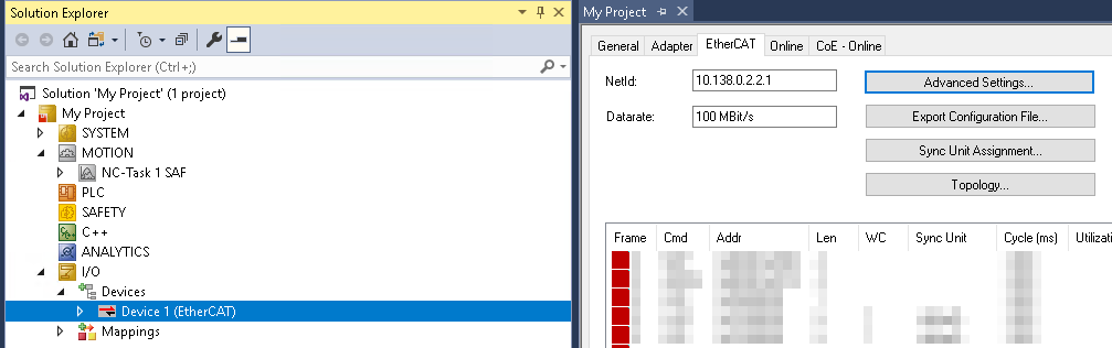
TwinCAT provides a dialog for configuring advanced bus settings around the EtherCAT state machine or distributed clock sync. To open it, double click the Device 1 (EtherCAT) entry in the Solution Explorer, select the EtherCAT tab in the center part of the screen and then select Advanced Settings....
Configuring distributed clock sync
Distributed clock (DC) sync is a mechanism to achieve highly accurate synchronization of the internal clocks of your real-time PC and the devices on the bus. Not all EtherCAT devices (such as very simple I/O modules) support DC. For those setups, DC is not needed.
However, if your bus contains real-time dependent devices, such as CiA/DS402 drives operated in cyclic synchronous position mode, we strongly recommend enabling clock synchronization to achieve reliable performance.
Once you opened the Advanced Settings... dialog find the Distributed Clocks sections in the tree view on the left side of the dialog.
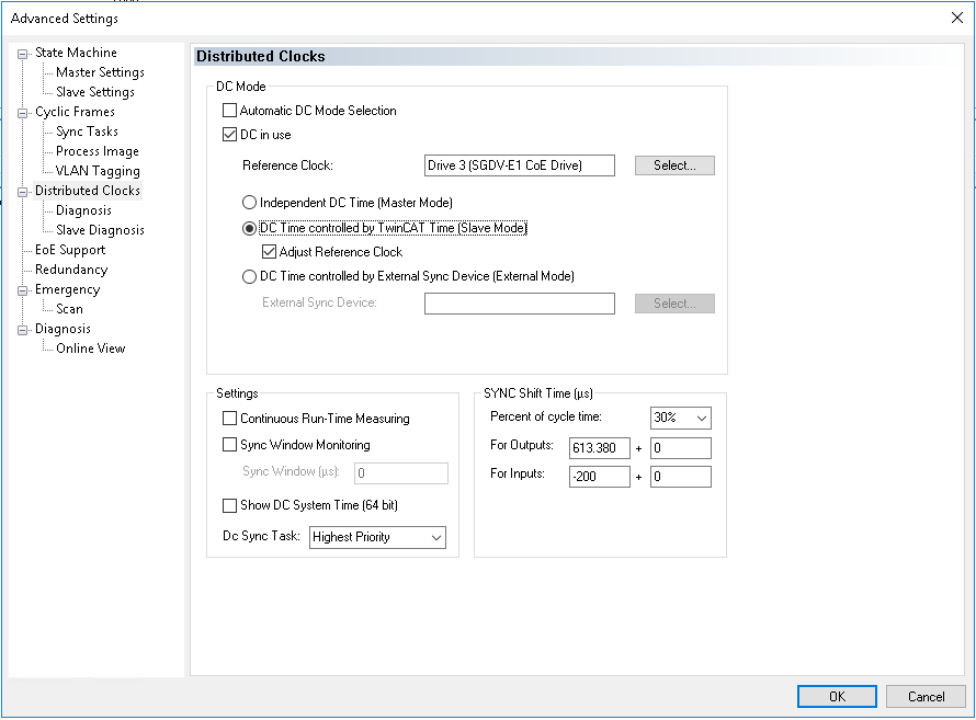
The automatic DC Mode Selection will most likely use Independent DC Time (Master Mode) which is not supported by Flowstate, since it would require the MainDevice to adjust its internal clock which could break the real-time interaction with other hardware modules.
Thus, you must select DC Time controlled by TwinCAT Time (Slave Mode) and make sure the box Adjust Reference Clock is ticked like in the screenshot below. This will tell the reference clock to adjust its internal clock and propagate the adjustment to the other DC-enabled SubDevices.
Afterwards, don't forget to set bus.distributed_clock.main_device_synchronization_mode to BUS_SHIFT as described in the hardware module configuration section.
For the Reference Clock TwinCAT typically selects the first DC-capable device on the bus. Changing is possible by clicking the Select... button, but this is typically not required.
Exporting the ENI file
Once the configuration is finished, you need to export the ENI file for later use in Flowstate, when configuring the EtherCAT Hardware Module.
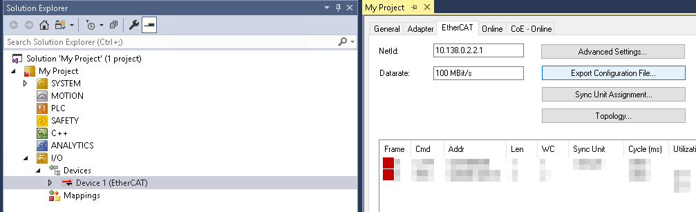
To export the ENI, double click the Device 1 (EtherCAT) entry in the Solution Explorer, select the EtherCAT tab in the center part of the screen and then select the Export Configuration File... button. Use the file dialog to find a location for the generated ENI file. You can directly upload this file into Flowstate without any additional changes.
Continue with the configuration of the EtherCAT hardware module.