EtherCAT diagnosis and troubleshooting
This article provides guidance on diagnosing and resolving issues related to the EtherCAT communication within Flowstate. Understanding these tools and error messages will help you maintain a robust and reliable control setup.
Diagnosis Options in Flowstate
Flowstate provides three primary tools for diagnosing EtherCAT issues: the Service Manager, the Real-time Control Panel and the EtherCAT Diagnostic Dialogs.
Service Manager
The Service Manager provides a central view of the equipment connected to Flowstate. This includes any real-time control service as well as hardware modules such as the EtherCAT hardware module. You can access the Service Manager by navigating to File | Service Manager in the Flowstate menu bar. See the Service Manager documentation for more information.
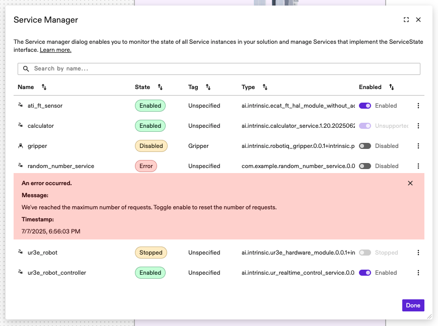
Locating the EtherCAT Module
Within the Service Manager, identify the hardware module representing your EtherCAT interface, by its name or type.
In case of an error, a corresponding message is displayed inside a red box in the respective row of the table.
Since hardware modules forward their errors to the real-time control service, the real-time control service may show a combination of errors from multiple connected hardware modules.
If you think the presented hardware module error is transient or has been fixed, try enabling the real-time control service by selecting the corresponding switch in the Enabled column. This will try to clear the fault and enable both the hardware module and the real-time control service if possible. If the error persists, see the example errors section below for advice or contact the Flowstate support.
Real-time Control Panel
The Real-time Control Panel appears once you select a real-time controlled item from the Scene view on the right side of the Flowstate screen. You can identify these items by the robot icon left to their name.

Once selected, the Properties view on the left shows the Control tab. In case of an error of either a hardware module or the real-time controller itself, this tab displays a red error box containing the error message. The message will be the same as the one shown for the real-time controller in the Service Manager.
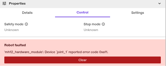
If you think the presented error is transient or has been fixed, select Clear to attempt to bring both the real-time control service and the hardware module to an Enabled state. If the error persists, see the example errors section below for advice or contact the Flowstate support.
EtherCAT Diagnostic Dialogs
Flowstate provides two diagnostic dialogs for EtherCAT:
- The EtherCAT Bus Status UI, that shows live data about the status of the bus and the connected bus devices.
- The SDO Export UI, which shows a live-updated view on SDO values and their configured interpretations.
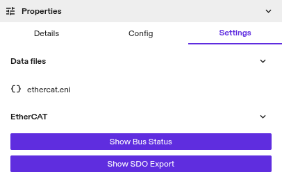
Both dialogs have dedicated buttons in the Settings tab on the left, after selecting your EtherCAT service in the Services tab on the right.
-
Show Bus status: Clicking this button opens the EtherCAT Bus Status UI. It shows the overall bus status, information about the bus topology as well as general information about the configured devices:
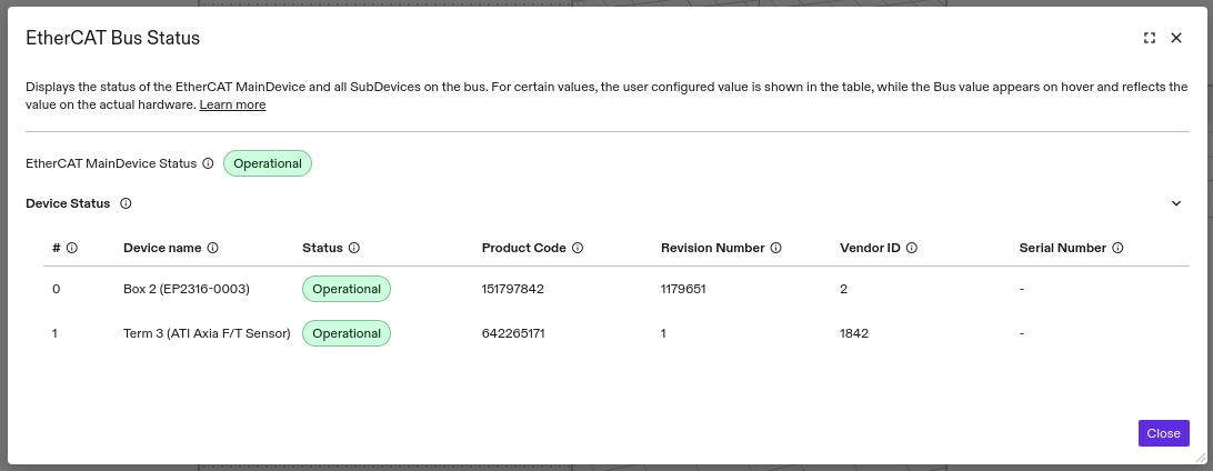 The order of the entries represents the logical bus order and the first column shows the bus index, which is necessary for the configuration of some devices, e.g. the force torque sensor.
If the bus does not match the configuration an asterisk (*) appears next to the affected value, with a tooltip showing the configured and the actual values: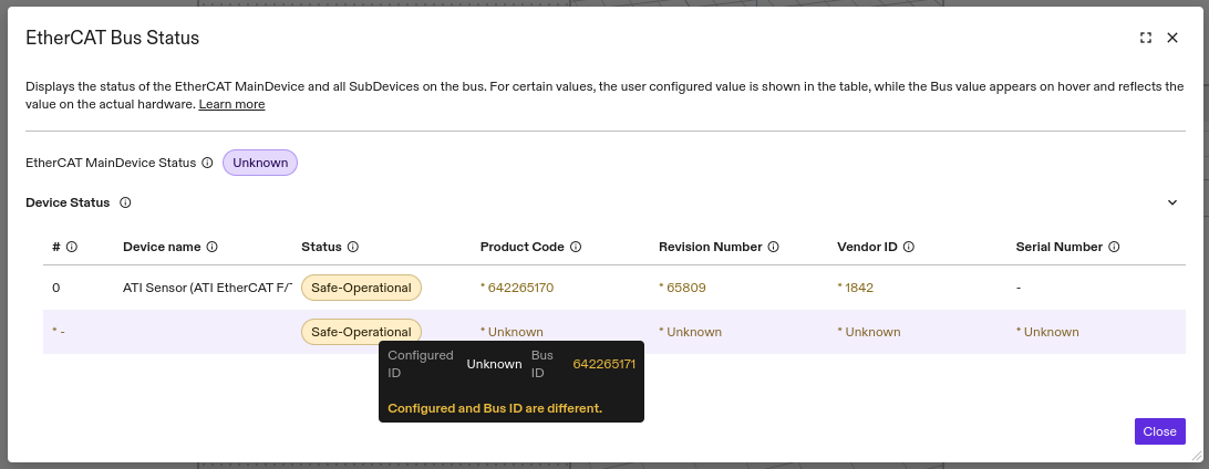 In this example, a single force-torque sensor was configured, but two entirely different devices were found on the bus. Such a situation will be accompanied by a bus configuration mismatch error.
 -
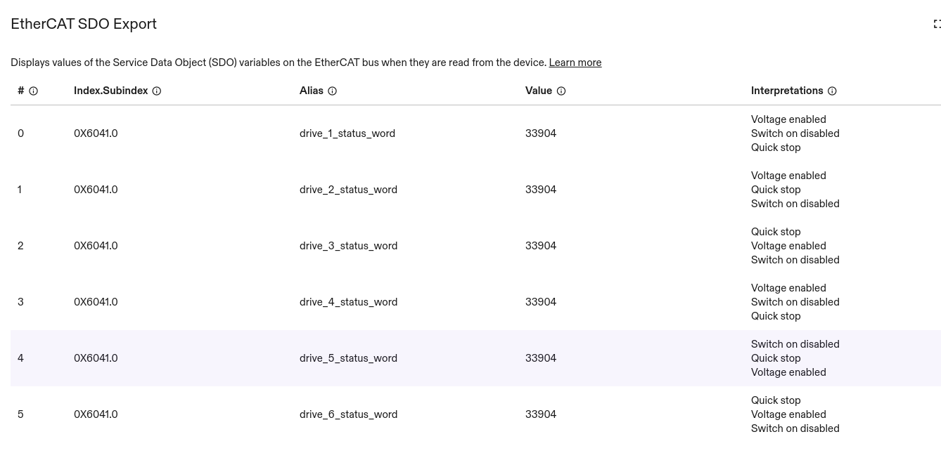
Open SDO export: This button opens a dialog that allows you to view the values of selected Service Data Objects (SDO) on the bus, along with human-readable interpretations of these values. See the Service Data Objects (SDO) configuration section for how to configure the display of these SDOs.
Example errors
Initialization with RTL8169 link layer failed: ERROR: Not found
Explanation: The EtherCAT hardware module is configured for the RTL8169 link layer, but the driver could not find a compatible network device. Ensure the device is connected and that the link layer is not already being used by another process.
Likely causes:
- The
bus.network_device.link_layer_preferencesfield has been set toRTL8169, but the network interface is not available or uses a different chipset. - Another instance of the EtherCAT Hardware Module or the EC-Engineer Web are already using this link layer.
Resolution:
- Use a different link layer, such as
INTEL_GBEand restart the real-time PC. - Delete the other instance (module or EC-Engineer Web), or configure your solution for multiple EtherCAT networks.
Cannot scan bus: ERROR: Ethernet link cable disconnected
Explanation: The system lost the ethernet link of the network device used for EtherCAT communication.
Likely cause:
- The EtherCAT cable has been unplugged or is broken.
Resolution:
- Replug the cable or replace the cable with a new one.
- Verify that the correct EtherCAT port is used following the setup guide
Cannot scan bus: ERROR: Time-out (0x98110010)
Example Logs:
I0617 15:31:27.730859       0 acontis_bus.cc:400] 690446.567762: PUBLIC: Initiating bus scan!
I0617 15:31:27.736736       0 acontis_bus.cc:579] 690446.573639: Transition from UNKNOWN to UNKNOWN took 0 cycles.
W0617 15:31:29.912731       0 acontis_bus.cc:2050] 690448.749634: Unknown Text (0x30004)
...
E0617 15:31:42.774214      16 hardware_module_runtime.cc:935] Initializing the module failed with: INTERNAL: Cannot scan bus: ERROR: Time-out (0x98110010)
=== Source Location Trace: ===
googlex/giza/icon/hal/lib/ecat/acontis_bus.cc:410
I0617 15:31:42.774204       0 hardware_module_runtime.cc:402] 690461.611107: Switching from kDeactivated to kInitFailed with message 'Cannot scan bus: ERROR: Time-out (0x98110010)'
Likely causes and resolution:
-
The bus is very large. This is the most likely reason if the configuration is new and untested.
Increase the
bus_scan_timeoutin the configuration of this hardware module.main_device: {
...
bus_scan_timeout {
seconds: 90
}
...
} -
One of the devices responds with an invalid message. This is the most likely reason if the configuration worked before.
Power cycle all EtherCAT devices on the bus. Leave the power off for ~10s so that all devices have time to fully de-energize and reset.
Timeout after 2s starting CyclicJobTask
Explanation: The system took an unusually long time to create an internal real-time thread for cyclic operations.
Likely cause:
- The real-time PC is experiencing an unusual high load.
Resolution:
- Retry or increase the timeout in
bus.main_device.thread_startup_timeout_ms.
Cannot set main_device state to SAFEOP: Bus configuration mismatch
Explanation: The system was unable to transition the EtherCAT bus from PREOP to SAFEOP due to the bus configuration differing from the actual devices on the bus.
Likely cause:
- The ENI file does not match the actual devices on the bus.
- One or more bus devices have lost power or are unresponsive.
- Bus devices have been removed or added without updating the corresponding ENI file.
Resolution:
- Make sure you uploaded an ENI file that matches the devices on the bus. Generate a new one and re-upload if needed.
- Ensure all bus devices are powered and that the power supply is sufficiently powerful.
Bus configuration mismatch: Ati F/T Sensor unresponsive
The system is reporting an EtherCAT Bus Configuration Mismatch in the Flowstate/Bus Status UI, where the mismatch coincides with the ATI sensor.
- The configuration is correct. This can be confirmed by using a replacement sensor.
- The ATI sensor is physically connected and the Status LED indicates that it is receiving power.
- The EtherCAT connection indicator on the sensor stays off.
- A short power cycles of the sensor does not resolve the issue.
Explanation:
An internal error stops the ATI sensor from communicating via EtherCAT.
Likely cause:
Unknown. Typically such issues are caused by faulty wiring, or issues with the power supply.
Resolution:
Remove power to the sensor for a longer amount of time, e.g. over night.
EtherCAT input/output variable variable_name not found
Explanation: The system is configured to access the variable variable_name from the process image as defined in the ENI file, but the process image does not contain a variable with that name.
Likely cause:
- The name
variable_nameis spelled incorrectly. - The process image has not been configured to contain the variable
variable_name.
Resolution:
- Check the correct spelling of
variable_namein the EtherCAT hardware module textproto configuration. - See the ADIO section for documentation about how to find variable names in the ENI file.
- Update and re-create the ENI file to include
variable_namein the process image.
Failed to enable DCM. Please check if the requested DCM mode is supported by the provided ENI or disable distributed clock entirely
Explanation: The system failed to enable the configured distributed clock MainDevice sync mode.
Likely cause:
- The module is configured to use the
BUS_SHIFTsync mode, but the ENI file has not been set up for this sync mode.
Resolution:
- Follow the ENI generation guide on how to enable
BUS_SHIFT. - Disable
DCMby settingbus.distributed_clock.main_device_synchronization_modetoOFF. Note that this is generally not recommended, especially when working with drives.
Call to {EnableMotion, DisableMotion, ClearFaults} failed: Timeout after ... ms
Explanation: The specified operation took an unusually long amount of time and was cancelled.
Likely cause:
- One or more bus devices did't complete the specified operation in the configured amount of time.
- [ClearFaults] The reason for the fault is still persisting and prevents the fault from being cleared.
Resolution:
- Try again, if you think this might be a temporary issue.
- [ClearFaults] Make sure that the reason for the fault is no longer present.
- Increase the
async_request_timeoutconfiguration parameter.
[CiA/DS402] Device `name` reported error code 0x...
Explanation: The device name reported an error through the configured error code bus variable. This error is only expected for CiA/DS402 devices for which the error_code bus variable has been defined.
Likely cause:
- The CiA/DS402 device experienced an error with the specified code.
Resolution:
- Consult the device manual or vendor for more information about the presented error code and resolution steps. For an example, see the troubleshooting section (15.12.1) of the Yaskawa Σ-7 Series, EtherCAT (CoE) Network Module manual.
- If you think the presented error is transient or has been fixed try clearing the fault through the Service Manager or Real-time Control Panel.
[CiA/DS402] Device `name` unexpectedly transitioned from state `one state` to state `another state`
Explanation: The device name unexpectedly transitioned to a different state in the CiA/DS402 state machine without request.
Likely cause:
- The device experienced an error or fault.
- The device was externally forced into a different state, i.e. from the safety system.
Resolution:
- Unless already shown, an attempt to clear the fault, should show the error code. Proceed with resolving a CiA/DS402 error code.
- Verify that no safety function keeps the device in a safe state.
EC_NOTIFY_SLAVE_INITCMD_RESPONSE_ERROR (1002, PS, download pdo 0x1A00 entry, Mailbox error)
Example logs:
0 acontis_bus.cc:2022] 162278.276401: EC_NOTIFY_MBSLAVE_COE_SDO_ABORT (0x10019)
0 acontis_bus.cc:146] 162278.276413: PUBLIC: Notify EC_NOTIFY_SLAVE_INITCMD_RESPONSE_ERROR (1002, PS, download pdo 0x1A00 entry, Mailbox error): ERROR SDO: Sub-index does not exist (0x98110053)
0 acontis_bus.cc:2022] 162278.276416: EC_NOTIFY_SLAVE_INITCMD_RESPONSE_ERROR (0x1000b)
0 acontis_bus.cc:146] 162278.284419: PUBLIC: SlaveSm(1002): Target state not reachable, EC_E_SLAVE_ERROR (0x98110024)
0 acontis_bus.cc:505] 162279.372407: Changing (asynchronously) from PREOP to SAFEOP state.
Likely cause and resolution:
If the ENI stopped working after adding PDOs, the most likely explanation is that the PDO definition contains too many entries for the device.
The solution is to remove PDOs. Maybe there are PDOs that are not used by the hardware module and can be removed without issues.
A general recommendation is to consult the device manual or vendor about requirements for the PDO definition (number of variables, padding, alignment, ...).
Advanced Diagnosis using Acontis Remote API Server (RAS)
The EtherCAT hardware module can be configured to start a Remote API Server (RAS), enabling introspection of the active EtherCAT main device and the devices on the bus.
Enabling RAS
RAS can be enabled by adding remote_api_server_settings to the hardware module configuration.
The server is started on the default port 7241.
bus: {
  // Enables the Remote API Server when present.
  remote_api_server_settings: {
    // When true, the module will ignore the following initialization errors to
    // allow analyzing the bus using RAS:
    //  * Bus scan errors
    //  * Distributed clock errors
    //  * SafeOp state transition errors
    // This allows scanning the bus with a wrong EtherCAT configuration.
    handle_init_errors_as_warnings: true
  }
...
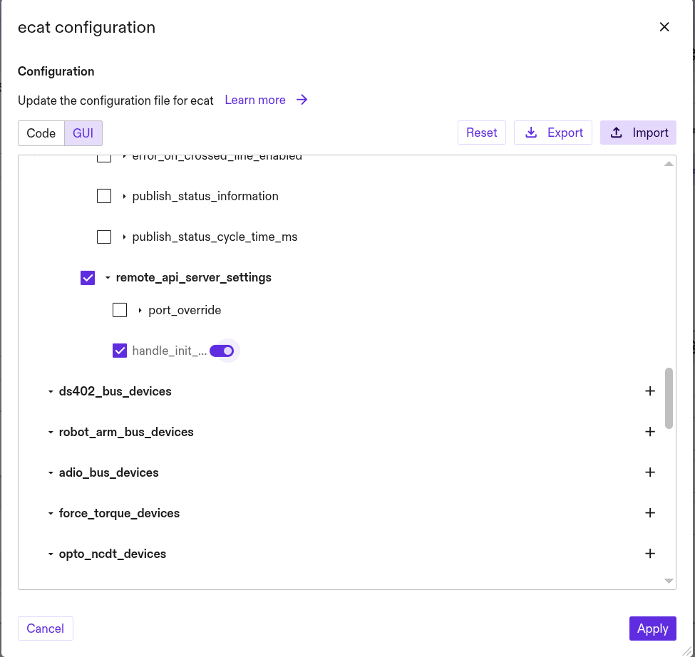
If multiple module instances expose RAS, the the optional parameter port_override of the remote_api_server_settings must be used to adjust the port.
Accessing RAS
RAS can be used by a service on the cluster, as well as tools on computers external to the cluster.
If you are not familiar with external tools, start with EC-Engineer Web from within the cluster.
The RAS server of the hardware module defaults to port 7241
From within the Cluster
Services like EC-Engineer Web can access RAS using the internal IP, as well as the external IP.
For single-node clusters. you can get the IP of the EtherCAT hardware module using the IPC manager.
- Open the dashboard from the IPC overview page:
⋮| Open dashboard - Select
All namespaces. - Search for the name of your EtherCAT hardware module. E.g.
ecat. - Use the
Cluster IPfrom Services (e.g.192.168.1.14).
For multi-node clusters, use the IP of the rtpc node.
Alternatively, you can use this command:
Adjust your-cluster-name and rs-ecat-0 to match your deployment.
- Replace
your-cluster-namewith the k8s context of your cluster.
In this example the hardware module is named ecat. So the parameter is rs-ecat-0.
- Prepend
rs. - Replace
_with-. - Append
-0.
kubectl get pod rs-ecat-0 --template={{.status.podIP}} --namespace=app-resources --context=your-cluster-name
An example result where the EtherCAT harware module uses the host IP is: 192.168.1.9.
Externally
This server can also be accessed using the workcell network using the IP address of the respective cluster node and the default port 7241.
On single node clusters, RAS is exposed on the IP address of the industrial PC (IPC).
On multi-node clusters, RAS is exposed on the the IP address of the realtime PC (RTPC).
The IP of the industrial/realtime PC can be found by:
- using flowstates ipc panel when configured with a static IP.
- your network managment interface, or by scanning the network, when IP addresses are assigned using DHCP.
- when the EtherCAT harware module uses the host IP, you can use the instructions for accessing RAS from within the Cluster.