KUKA RSI setup
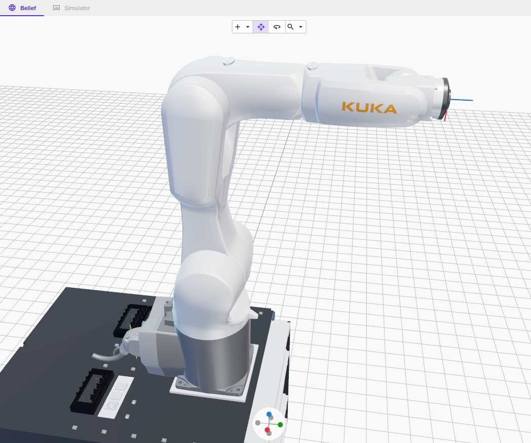
KUKA industrial robots (e.g. AGILUS KR6) can be controlled through Intrinsic Flowstate using the RobotSensorInterface (RSI) option provided by KUKA.
In case your robot was set up with Intrinsic Flowstate before Feb. 2024, visit the previous version instructions page.
This guide does not include guidance on safety. Set up adequate safety systems and conduct all risk assessments before deploying to real hardware.
Overview
The Intrinsic hardware module for KUKA robots uses the KUKA features RobotSensorInterface (RSI) and Ethernet KRL Interface (EKI) to communicate with the KUKA Robot Control(er) (KRC). The main communication channel is RSI, which is the realtime control feature of KUKA and is used for motion execution. EKI is used to retrieve additional non-realtime status information and sending control commands such as enable, disable or clear faults.
The setup consists of the following steps:
- Setting up the network wiring between KUKA Robot Controller (KRC) and Intrinsic IPC
- Setting up the I/Os for external control of a KUKA robot
- Configuring the KUKA WorkVisual project
- Adding the assets in Flowstate
- Enabling the robot for use with Flowstate
Prerequisites
- Basic knowledge about Intrinsic Flowstate
- Basic knowledge about KUKA robots configuration and usage (KUKA Start-Up Course)
- Flowstate-supported KUKA industrial robot that is operational (safety is set up (the robot is in a safety cell) and KUKA programs can be executed)
- One of
- KUKA C4 controlbox (KRC) with KUKA System Software 8.6 and RobotSensorInterface 4.X, Ethernet KRL 3.1 options
- KUKA C5 controlbox (KRC) with KUKA System Software 8.7 and RobotSensorInterface 5.0, Ethernet KRL 3.2 options
- KUKA WorkVisual 6.0 running on a notebook or desktop pc with an Ethernet connection to the KUKA C4's X69 port or to the KR C5's XF1 port, using DHCP
- KUKA compatible I/O device. Recommedation Beckhoff
EK1100, EL1008,
EL2008
(example KUKA configuration is provided in the Intrinsic base option package) - Cluster with Intrinsic stack
- Flowstate solution that is configured for this Intrinsic cluster
- 1 RJ45 CAT6 network cable
In a nutshell for experienced KUKA robot users
- Install the Intrinsic option packages:
- Base package
- Extended package
- The I/O configuration available in the Extended package
- Connect an Ethernet cable to the robot Ethernet port of the Intrinsic IPC and to the KLI port of the KRC
- Wire up the EK1100, EL1008 and EL2008 and connect outputs 1-3 of EL2008 to inputs 1-3 of EL1008 with a wire each
- Adjust the IPC network configuration following the network setup section
- Follow the Flowstate setup in section "Asset configuration"
- Set the robot to
Externalmode using the teach pendant - Use the robot with Flowstate
For testing, you can skip the I/O setup and enable the robot using the teach pendant.
More detailed information is given in the following sections.
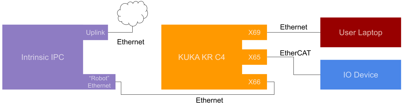
Step 1: Network wiring between Intrinsic cluster and KUKA robot controller
The KUKA KR C4 needs to be connected to the Realtime PC (RTPC) of the Intrinsic Cluster. This means the robot Ethernet port needs to be connected to the KUKA Line Interface (KUKA KLI), on the KR C4 to the X66 port.
Step 2: KUKA robot controller setup
KUKA features are often provided as KUKA option packages, such as
SafeOperation or RobotSensorInterface.
Intrinsic provides two KUKA option packages for convenient installation and configuration of the KUKA Robot Controller (KRC):
- A Base package containing basic configuration files for RSI and Ethernet KRL Interface (EKI)
communication with the Flowstate environment.
Download Base package - An Extended package based on the base package but containing additional
configuration that are more likely to be in conflict with controller
configurations when the KRC project has already some pre existing configuration changes (see option package description section for a description about the contents of the option package).
Download Extended package
For easy setup it is recommended to install both option packages. The extended option package should only be skipped if it causes problems with e.g. the existing network configuration or IO mappings.
Create a backup of your WorkVisual project before installing or updating any of the option packages since the KUKA option package installer overwrites existing files that were added or modified manually.
When installing the Intrinsic extended option package, it will overwrite the following elements:
- The submit interpreter at position three (the first user defined submit interpreter)
- The network configuration of virtual devices named
KLIandRSI(case-insensitive) - The KUKA signals
$DRIVES_ON,$MOVE_ENABLEand$CONF_MESS
Install the Intrinsic option package just as other KUKA option packages are installed.
See the KUKA WorkVisual 6.0 manual (section 6.30) for a detailed description on the process.
Physical I/O device for external control
To enable, disable and clear faults from an external source, in this case Flowstate, KUKA requires to use physical I/Os.
This means 3 outputs need to be wired onto 3 inputs and configured and mapped on the KUKA controller or in WorkVisual.
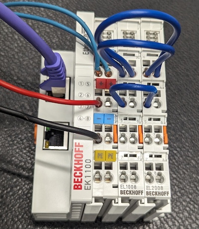
The Intrinsic extended option package provides such a configuration and mapping for the recommended I/O device combination Beckhoff EK1100, EL1008 and EL2008 connected using EtherCAT to the KRC at port X65.
Use the first three outputs and inputs to match the provided configuration as shown in the following figures.
The configuration and mapping can be installed in the same way an option package is installed into a WorkVisual project:
By dragging the Intrinsic I/Os using EK1100, EL1008, EL2008 component from the Options catalog on the controller in WorkVisual.
The I/Os must be mapped on indices 421-423.
Don't change the I/O indexes during installation, or you need to adjust the corresponding KRL signals as well!
I/O wiring diagram for external KUKA control
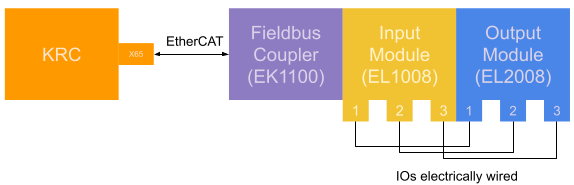
I/O Wiring example for external KUKA control
Usage of other I/O devices
It's possible to use other I/O devices, but the detailed configuration is out of scope for this documentation.
The minimal requirements are:
- The I/O devices need to be compatible with the KUKA KRC at hand and to be configured in WorkVisual.
- Three of the digital inputs and outputs of the device need to be mapped to the
KR C I/Oswith indexes421-423, each for inputs and outputs.
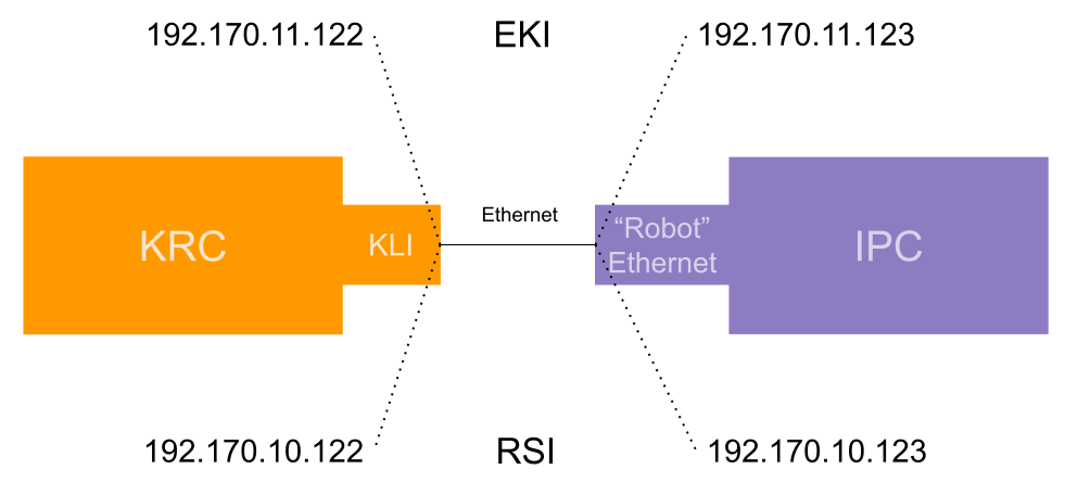
RSI/EKI virtual network card (NIC) configuration
Flowstate uses EKI and RSI to communicate with the KRC.
KUKA requires using different virtual network devices for these two channels.
Therefore, the Intrinsic extended option package installs two virtual network devices:
- RSI with the IP
192.170.10.122and subnet mask255.255.255.0 - EKI and potential other non-realtime communication with the IP
192.170.11.122and subnet mask255.255.255.0
Analogously, the Intrinsic IPC needs to have two virtual NICs on the non-EtherCAT robot NIC with fitting IP addresses, for example 192.170.10.123 and 192.170.11.123.
It is recommended to use the suggested IPs. Otherwise, there might be a conflict in C:\Config\User\Common\SensorInterface\RSIEthernetConfig.xml everytime the Intrinsic option package is updated.
If the used IPC contains a single compute node (i.e. PC) the IPC Manager on the Flowstate portal can be used to configure the IPC's network configuration. For IPCs with multiple compute nodes the command line tool inctl has to be used from the devcontainer.
- Tier 1 and 2 IPC (single node)
- Tier 3 IPC (multi node)
IPCs with a single compute node can be configured from IPC Manager on the Flowstate portal as we have already learned in RTPC Network Configuration.
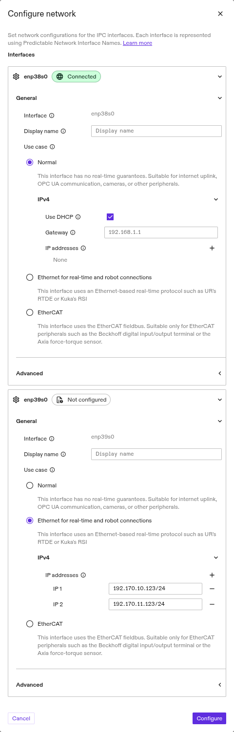
To control the system state of a KUKA robot from Flowstate we need to configure a second virtual network card on the physical network card that is connected to the KUKA KRC.
In the IPC Manager, find the ethernet device which is set-up as Ethernet for real-time and robot connections (i.e. enp39s0 as in the image below). Click on the + button besides IP addresses to add the second virtual network card as shown in the following picture.
When using the default configuration of the Intrinsic option package, the IPs and network mask need to be 192.170.10.123/24 and 192.170.11.123/24.
After pressing Configure the IPC will apply the new network configuration. Now the IPC should be able to ping the KUKA KRC. You can try by accessing the ping tool via the overflow menu (⋮) next to your IPC in the IPC manager.
The configuration of an IPC with multiple compute nodes needs to be done from the command line using inctl from the Intrinsic dev container in Visual Studio Code.
You can also set up Tier 1 and Tier 2 IPCs from the command line. In this case, $RTPC_NAME is the same as $CLUSTER_NAME.
The IPs can be set with the following commands.
First, get the current configuration with:
inctl device config get --org $ORG --device_id $RTPC_NAME --cluster_name $CLUSTER_NAME
The output should look similar to:
Current state:
 enp0s31f6: [192.168.1.15/24]
 enp6s0: [169.254.4.53/16]
 enp7s0: []
 enp8s0: []
Current config: {"en*":{"dhcp4":true,"gateway4":"","dhcp6":false,"gateway6":"",  "mtu":0,"nameservers":{"search":null,"addresses":null},"addresses":null,  "realtime":false}}
The example output uses a wildcard (en*) for the network cards.
- Split the configuration into explicit entries for every network card
- Copy the default configuration for the non realtime NIC (
enp0s31f6in the example)
- Copy the default configuration for the non realtime NIC (
- Copy the JSON configuration string and replace the
addressesfield value of the NIC connected to the KRC, usually calledenp6s0, with["192.170.10.123/24", "192.170.11.123/24"] - Furthermore, set the
realtimeattribute for that NIC totrue
Example Configuration (do not copy this configuration since the network interface names might be different on your IPC):
# Do not copy since the network interface names might be different on your IPC
inctl device config set --org $ORG --device_id $RTPC_NAME --cluster_name   $CLUSTER_NAME \
'{"enp0s31f6":{"dhcp4":true,"gateway4":"","dhcp6":false,"gateway6":"","mtu":0,  "nameservers":{"search":null,"addresses":null},"addresses":null,  "realtime":false},\
"enp6s0":{"dhcp4":false,"gateway4":"","dhcp6":true,"gateway6":"","mtu":0,  "nameservers":{"search":null,"addresses":null},"addresses":["192.170.10.123/24",  "192.170.11.123/24"],"realtime":true}}'
Apply the new configuration by replacing $config with the configuration JSON string in the following command and execute it:
inctl device config set --org $ORG --device_id $RTPC_NAME \
  --cluster_name $CLUSTER_NAME '$config'
After executing the command, check with the previous device config get command that the correct configuration was applied.
The inctl device config get command might show an empty IP-list for a NIC when
- The other side (e.g. KRC) is not turned on or the NIC is not working correctly. Try rebooting the KRC
- No cable is plugged into the network port of the NIC
- The cable is in the wrong port
Deploy the changes on the robot
Deploy all changes onto the robot using WorkVisual.
Step 3: Add the assets in Flowstate
To connect KUKA robots within Flowstate, you must add a KUKA hardware module driver asset and its respective real-time control service to Flowstate, and adapt the configuration.
To add the assets, follow the guide at Add a robot to Flowstate.
During following the guide, choose the "KUKA RSI real-time control service" and the hardware module driver for your specific robot model.
Modify the local_rsi_host IP and enable external control
The default configuration already contains the correct configuration for the default IP and for usage with the external control setup as described above.
If you're not using the default IP or lack the EKI configuration, adjust the hardware module driver's settings as follows.
Configure the hardware module to listen on the realtime NIC for RSI messages:
Select the hardware module instance (by default, robot) from the tree-view of
the Scene and click the Config tab (at the left side of the Flowstate
window).
In the text edit input field, you need to replace the field local_rsi_host
with the correct IP of the used NIC of the Intrinsic RTPC in the configuration
file. This is the same IP as used in the RSI Ethernet configuration: (default) 192.170.10.123
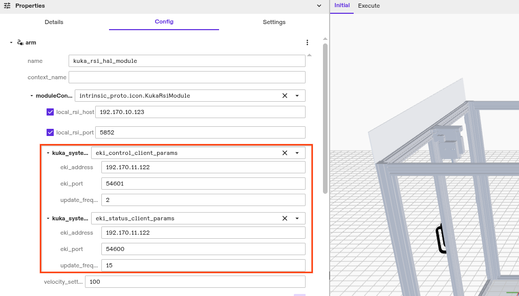
To activate status reporting and external control using EKI, add the following snippet on the same nesting level as local_rsi_host. The IP used here is the IP of the virtual NIC named "KLI" on the KUKA KRC (not the "RSI" NIC). The following configuration snippet fits to the IP used in the Extended Intrinsic option package.
- Textual Config
- GUI
Insert the highlighted block into the textual configuration:
# ...
module_config: {
  [type.googleapis.com/intrinsic_proto.icon.KukaRsiModule]: {
    local_rsi_host: "192.170.10.123"
    # ...
    eki_control_client_params: {
      eki_address: "192.170.11.122"
      eki_port: 54601
      # Update rate of the EKI control telemetry. Recommended not to
      # change. Limited to 15 Hz due to EKI response time.
      update_frequency: 2
    }
    eki_status_client_params: {
      eki_address: "192.170.11.122"
      eki_port: 54600
      # Update rate of the EKI status telemetry. A rate of 10+ is mainly
      # needed for a smooth visualization during teach pendant jogging.
      # Recommended not to change. Limited to 15 Hz due to EKI response
      # time.
      update_frequency: 15
    }
    # ...
  }
}
# ...
Finally, click Save to store your changes in the solution.
(Optional) Customize digital inputs and outputs
The RSI context installed with the Intrinsic base option package contains four preconfigured inputs and two preconfigured outputs for custom use.
This can be extended to a maximum of ~50 inputs and ~50 outputs.
RSI allows 64 inputs and 64 outputs in total and the control commands and telemetry need around 10.
Each KUKA input must be connected to an input of the RSI Ethernet object.
Each KUKA output must be connected to both, an input and output of the Ethernet
object.
The outputs that are connected to inputs contain the actual values
of an output, not just the set values.
Each input and output must use the Bit as the value of DataType field.
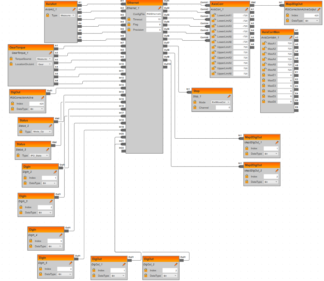
This configuration is demonstrated in the RSIContext for some inputs and outputs and shown in the next figure.
Add the same I/Os to C:\Config\User\Common\SensorInterface\RSIEthernetConfig.xml and follow the demonstrated pattern:
  <!-- Customizable digital inputs/outputs.
  Input Tags need to be of format "DigIn.DI<number>",
  where the number needs to be ascending without gaps.
  Outputs must be similarly tagged "DigOut.DO<number>" -->
  <ELEMENT TAG="DigIn.DI1" TYPE="LONG" INDX="16" />
  <ELEMENT TAG="DigIn.DI2" TYPE="LONG" INDX="17" />
  <ELEMENT TAG="DigIn.DI3" TYPE="LONG" INDX="18" />
  <ELEMENT TAG="DigIn.DI4" TYPE="LONG" INDX="19" />
  <ELEMENT TAG="DigOut.DO1" TYPE="LONG" INDX="20" />
  <ELEMENT TAG="DigOut.DO2" TYPE="LONG" INDX="21" />
There must not be any gaps in the numbering.
The TAG names in RSIEthernetConfig.xml are case-sensitive.
Make sure to map those inputs and outputs to appropriate fields in the Mapping
view in WorkVisual as needed for your specific application (see
WorkVisual section 9.4 "Mapping the bus I/Os").
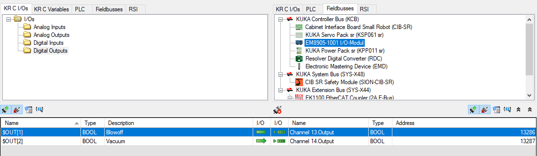
Note that you need to map to KUKA's $IN[] and $OUT[] variables in the "KR C I/Os" tab
since the provided RSIContext.rsix file uses the RSI objects DigIn and DigOut.
This way the state of the I/Os can also be inspected on the teach pendant.
The following figure shows an example for mapping the integrated outputs of a KR6 onto the
first 2 entries of the "KR C I/Os" as used in the provided RSIContext.rsix file:
Those indexes of the KUKA $OUT variable are to be specified in the RSIVisual editor window for the DigOut and Map2DigOut objects as well:
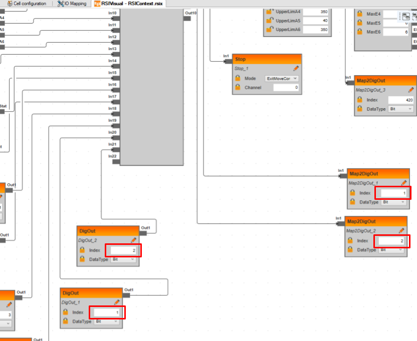
Configure the inputs following the same pattern.
The hardware module configuration file (see
custom IP configuration) must have the same number of
digital_input_names and digital_output_names entries as inputs and outputs
are configured in C:\Config\User\Common\SensorInterface\RSIEthernetConfig.xml.
The names can be freely chosen.
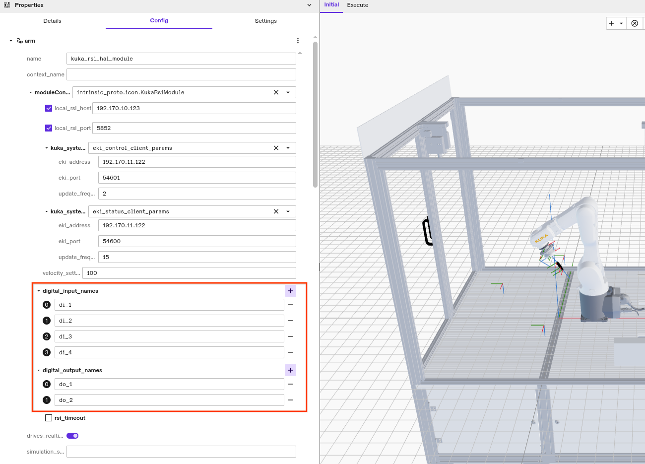
Example: For four inputs and two outputs insert the following lines into the protobuf configuration file:
- Textual Config
- GUI
Insert the highlighted block into the textual configuration:
# ...
module_config: {
  [type.googleapis.com/intrinsic_proto.icon.KukaRsiModule]: {
    local_rsi_host: "192.170.10.123"
    # ...
    digital_input_names: ["di_1", "di_2", "di_3", "di_4"]
    digital_output_names: ["do_1", "do_2"]
  }
}
# ...
Those digital inputs can be observed using the
dio_wait_for_input skill.
Digital outputs can be changed using dio_set_output skill.
Additionally, both can be used with the ICON ADI/O action.
(Optional) Adjust custom hardware module resource name
In case the hardware module was renamed to anything else than robot, the default configuration for the realtime control service is no longer valid.
To change the configuration, select the realtime control service asset from the scene view and click Config.
This will display the configuration of the asset.
In there, change the values of hardware_resource_name and world_robot_collection_name to the name of the KUKA hardware module resource.
name override:If the hardware module configuration uses a name override, the module_name and hardware_module_names in the Realtime control service configuration needs to be set to the value of the override.
hardware_resource_name and world_robot_collection_name need to be set to the name of the KUKA hardware module resource.
Step 4: Enable the robot
When the hardware module has been deployed, it immediately starts listening for the RSI data from the KUKA KRC.
Robot safety training and an introduction to the KUKA robot system is required before executing the following steps!
eki_control_client_params needs to be set in the protobuf configuration.
Otherwise, the hardware module assumes it supposed to run without EKI.
In that case, see section "Enable the Robot using the Teach Pendant".
Switch to External (or Ext) operation mode using the physical turn switch on the KUKA teach pendant.
The robot enables automatically when there is no fault.
Faults can be cleared in two ways.
Using the robot control panel
- Open the robot control panel in Flowstate by selecting the robot in the 3D view and clicking on Control on the left side of the window.
- Check if there are any faults active and remedy the cause if necessary. The fault might not be active anymore, but it will still be shown to the user until it is acknowledged.
- Click Clear to clear the faults. If the faults can be cleared and the RSI connection is stable, the robot control stack will enable itself. Otherwise, the active fault will be shown.
Using the service manager
- Open the service manager in Flowstate by selecting File | Service Manager. Check if there are any faults active and remedy the cause if necessary. The fault might not be active anymore, but it will still be shown to the user until it is acknowledged.
- Find the entry for the realtime control service (
arm_controllerin the animated image below) and flip the switch in the Enabled column to Enabled. If the faults can be cleared and the RSI connection is stable, the robot control stack will enable itself and the hardware module. Otherwise, the active fault will be shown.
Legacy mode: Enable the robot using the teach pendant
In case you are not using EKI and the physically looped I/Os, you can enable the robot using the teach pendant.
In this case, it is important that the eki_control_client_params value does not exist in the protobuf configuration of the hardware module.
Follow these steps to enable the RSI using the teach pendant:
-
Release all emergency stops (on the teach pendant, cell etc.)
-
Confirm all messages
-
Switch to
automaticmode (physical turn switch) -
Choose the
RSI_MCprogram from the file view and press the Select button at bottom of the screen (Do not press the Open button since this opens the program for editing)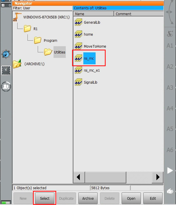
-
Enable the drives (Press the button with
Oat the top. In the dialog pressIand wait until theO-button becomes a greenI-button. If the drives are already enabled, you see a greenIin place of theO.)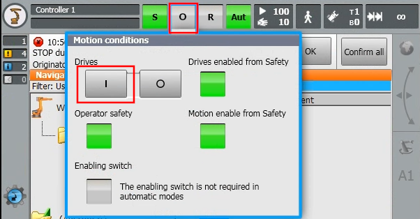
-
Press the green Play button (left of screen) until the cursor arrives at
RSI_MOVECORR()
Now you should be able to move the robot in Flowstate. You may first need to Clear faults in Flowstate.
Troubleshooting
This section describes typical obstacles a user might encounter when using KUKA robots.
General Motion Enable message on teach pendant
A digital output signal must be connected to the KRC that is mapped to the input signal $MOVE_ENABLE.
In many cells this input is always active.
If not, the "General Motion Enable" message is shown.
If the Intrinsic extended option package is installed, the $MOVE_ENABLE input signal is mapped to $IN[421] and waits for this input to be active (i.e. true or 1).
Robot moves after teach pendant jogging
This is intended behavior of a KUKA robot. It does a BCO motion to the last known position.
The RSI KRL program needs to be reset when using teach pendant jogging.
This is done automatically in EKI controlled mode.
Installation of Intrinsic Extended Option Package fails with Cannot edit KLIConfig.xml
The PC where WorkVisual is running likely does not have the XML library installed.
There should be a Windows window to install it.
Afterwards WorkVisual needs to be restarted.
Flowstate reports a version mismatch as fault in the control panel
The version of the hardware module and the Intrinsic option package must match in the major and minor version. Otherwise, the robot cannot be enabled.
Update both, the IPC and the Intrinsic option package to the same version (Check KRC Setup or Archive).
Flowstate reports that the I/O count does not match
Flowstate can report the following message when the I/O configuration on KRC and Flowstate does not match:
The number of received inputs (4) does not match the number of configured digital inputs (0).
This happens when the configuration in the I/O configuration in C:\Config\User\Common\SensorInterface\RSIEthernetConfig.xml does not match the configuration in the hardware module.
To fix this, make sure both configurations have the same number of inputs and outputs and redeploy the hardware module or WorkVisual project.
Flowstate reports Could not bind to socket
In case Flowstate reports a message like Could not bind to socket: 192.170.10.123:5852: Cannot assign requested address, the IP of the NIC on the Intrinsic IPC used for communication with the KUKA KRC does not fit to the configuration.
In this example, the IP 192.170.10.123 was configured in the hardware module configuration, but there is no NIC with that IP on the IPC.
This can be resolved in two ways, depending on your network configuration:
- Adjust the IP of the NIC using
inctlas described in Ethernet configuration section - Adjust the IP used for RSI/EKI communication in the hardware module configuration as shown in the Add asset section
Flowstate reports RSI start timed out
This error message can have several causes:
- A common reason after changing project settings on the KUKA robot is that the network card on the KUKA is not working anymore.
- This can often be solved by rebooting the KUKA controller.
- The RSI_MC KRL program could not be started on the teach pendant.
- Investigate error messages on the KUKA teach pendant for more information.
- A wrong network IP is configured on KUKA or Intrinsic IPC side for the KUKA RSI connection.
- Align the IP addresses to be in the same network and align the configuration in the hardware module config on Flowstate side and the
RSIEthernetConfig.xmlon KUKA side.
- Align the IP addresses to be in the same network and align the configuration in the hardware module config on Flowstate side and the
RSI object configured incorrectly on teach pendant
In general, RSI object configured incorrectly means that the KUKA runtime has found an issue within the RSI configuration.
Inspect the C:\Config\User\Common\SensorInterface\RSIEthernetConfig.xml and the
C:\Config\User\Common\SensorInterface\RSIContext.rsix for any invalid configuration and
follow the instructions on the teach pendant linked with the error message (if available).
If all else fails, re-installing the IntrinsicBase option package will restore the original state of the RSI files.
Contents of the Intrinsic option packages
In case of conflicts during installation or if you would like to know what you are installing on your KRC, the contents of the Intrinsic option packages are described below.
The Intrinsic base option package
The Base package specifies the necessary dependencies to function with Flowstate and their compatible versions.
It contains files for
- the RSI context
- the RSI XML protocol definition
- two EKI protocol definitions
- the RSI KRL program
- the Intrinsic submit interpreter for EKI communication and associated global variables
The Intrinsic Extended option package
The Extended package depends on the base package and contains some file modifications:
- Replaces existings KLI/RSI (case-insensitive) virtual NICs from the KRC with configuration suitable for Flowstate's default configuration
- Replaces the KUKA signals
$DRIVES_ON,$MOVE_ENABLEand$CONF_MESSwith values the Flowstate EKI integration expects - Starts the Intrinsic submit interpreter at position 3
Archive of option package releases
v1.1.1 - Aug. 2025
Release Notes
- Fix error in intrinsic.sub when no messages are present
v1.1.0 - Sep. 2024
Release Notes
- Add support for setting the payload from Flowstate on the KRC
- Fix KSS error message numbers null termination in XML string
- Fix KSS dependency version for KR C5 (KSS 8.7.x)
v1.0.0 - Feb. 2024
Release Notes
Initial release