FANUC Stream Motion setup
FANUC robots are supported on Intrinsic Flowstate using FANUC's Stream Motion (J519) package. A list of available software packages for FANUC robots and how to purchase them can be found on FANUC's website.
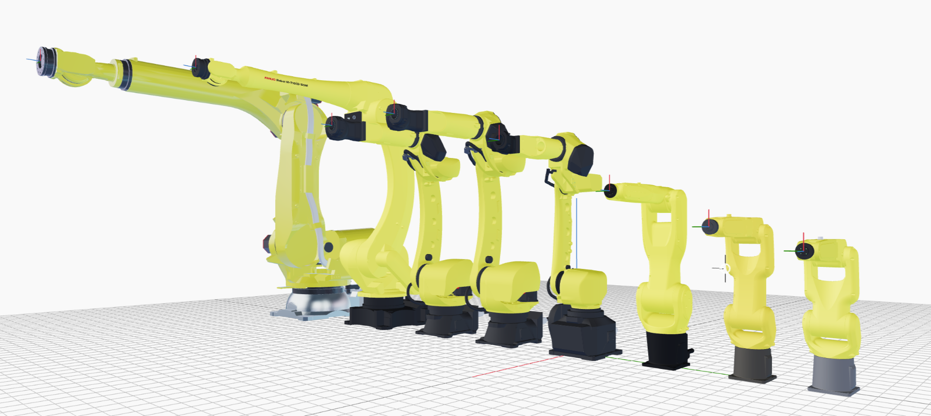
As of the time of writing, Intrinsic has configured hardware modules drivers for the following kinematics:
This guide walks you through onboarding the LR Mate 200iD/7L, and is applicable to all listed FANUC robots.
This guide does not include guidance on safety. Set up adequate safety systems and conduct all risk assessments before deploying to real hardware.
Prerequisites
In order to follow the guide successfully, it is assumed that the FANUC control box is properly installed and set up with the OPC-UA service package (R553) as well as Stream Motion (J519). The former is typically included within the EU Standard Setting (R651) setup and has to be explicitly added with North America Setting (R650). Both packages must be available to correctly control the robot through Intrinsic Flowstate. The Stream Motion package and OPC-UA package has been tested with controller versions v9.40P/53 and v9.40P/55. While newer versions are likely compatible, they haven't been officially verified. Older versions might be incompatible or contain breaking bugs.
Step 1: Configure network connection between Intrinsic cluster and FANUC control box
The actual teach pendant instructions below might slightly differ for every robot control box depending on which packages are installed. The R30iB control box has two inbuilt network ports which have to be configured with a static IP to connect to Intrinsic's real time compute (RTPC).
The stream motion interface works over a low level UDP socket connection.
Internally, FANUC's network port #2 is higher prioritized so configure that port
with Intrinsic's internal robot IP. On the FANUC R30iB control box the physical
Ethernet port is labeled CD38B.
On the teach pendant select MENU -> Setup (6) -> SETUP 3 -> Host Comm (9) -> TCP-IP
Switch to Port 2 by pressing PORT in the status bar. Then configure the IP to
192.170.10.1 and finalize by pressing INIT in the status bar (you might have
to press the > to see INIT).
You can verify the connection by configuring a local hostname such as
   Host Name (LOCAL)     Internet Address
   1           rtpc         192.170.10.123
Select that rtpc and press PING in the status bar to verify a connection to
the Intrinsic cluster (RTPC).
Step 2: Deploy FANUC robot assets with geometry information in Flowstate
To connect FANUC robots within Flowstate, you must add a FANUC hardware module driver asset and its respective real-time control service to Flowstate, and adapt the configuration.
To add the assets, follow the guide at Add a robot to Flowstate.
When following the guide, choose the "FANUC real-time control service" and the hardware module driver for your specific robot model.
Step 3: Let Flowstate configure the FANUC control box
Create an image backup and/or all-of-the-above backup of your FANUC control box before proceeding (see FANUC manuals, e.g. MAROUHT9102171E REV E chapter 12.6)
The FANUC hardware module driver is able to set up the configuration needed to control the FANUC via Stream Motion remotely via OPC-UA and FTP. During this setup process, Flowstate will:
- Set all system variables needed for operation with Flowstate.
- Upload the IO mapping file to
MD:\DIOCFGSV.IO(the existing file will be backed up toFRA:\flowstate\DIOCFGSV_IO.bakon the FANUC control box). - Upload a robot program to
MD:\PNS0003.LSif it doesnt exist yet. If it exists already, it will perform a basic validity check to avoid common misconfigurations.
For more details see the configuration details section.
The following configuration has been tested a FANUC control box using factory-defaults. Due to the large number of FANUC system variables there might be configurations that are incompatible with Flowstate and are not handled here.
The following setup dialog will walk you through the automated configuration of the FANUC control box with Flowstate.
-
If your robot has previously been used with Flowstate, the first step is to place the robot in the motion-disabled state—either by running the
Disable robotaction or by pressing the e-stop. In case you are setting up the robot with Flowstate for the first time, you can skip this step. -
Once the robot is disabled, select the robot in the 3D scene or the scene tree. In the left side panel select then Settings and look for the section Robot control box setup.
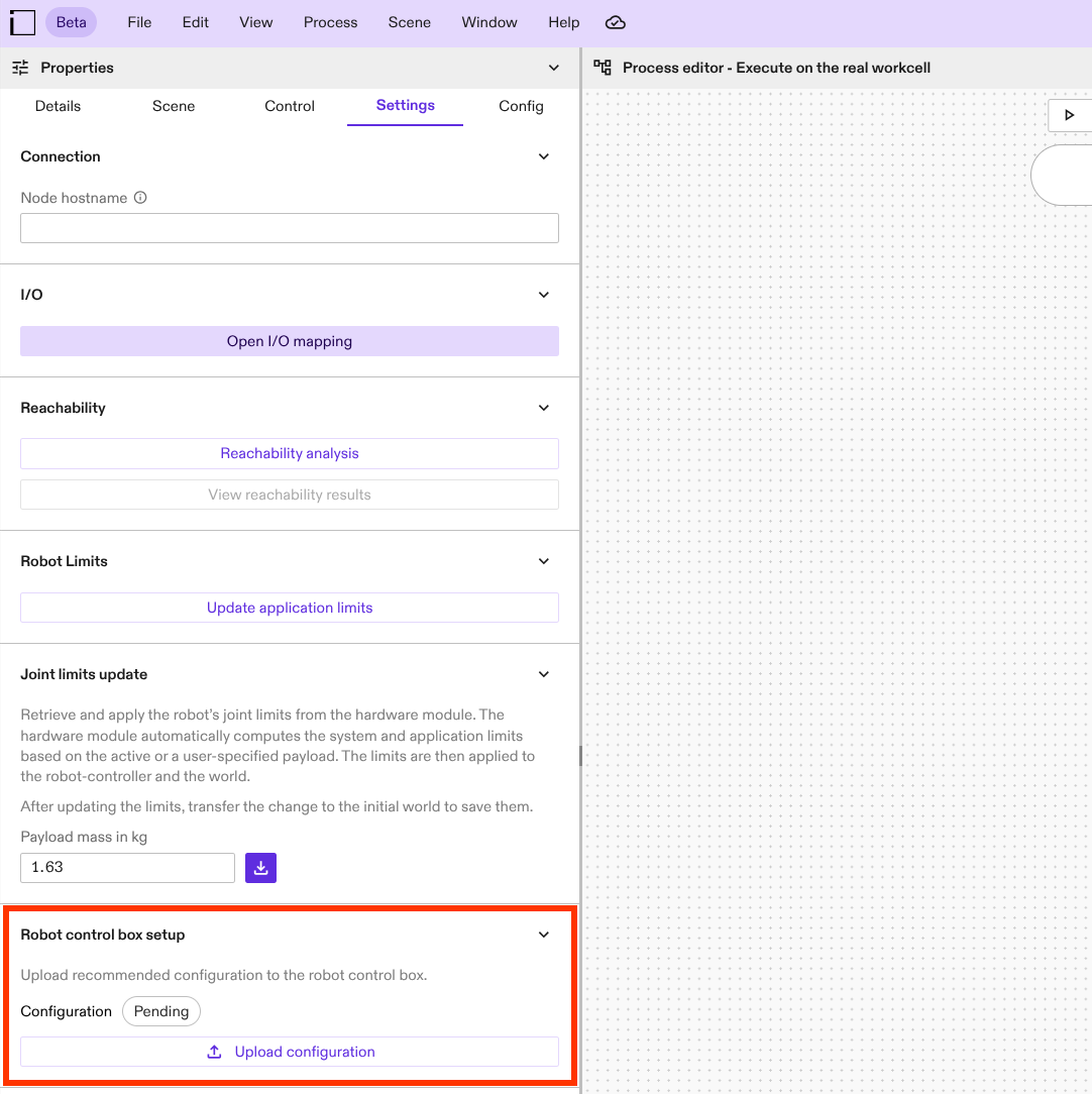
A label indicates the current state of the robot control box configuration:
- Pending: The service for determining the robot control box configuration has not been run yet; the state of the configuration is not known.
- Recommended: The configuration of the robot control box already corresponds to the recommended values for working with Intrinsic Flowstate.
- Not recommended: The configuration deviates from the one recommended by Intrinsic Flowstate. It might still work but using such a configuration is commonly discouraged.
- Error: An error occured while trying to contact the robot control box. Make sure that you are connected to the robot control box and proceed with the configuration.
Click on the Upload configuration button to proceed with inspecting the current configuration and uploading the defaults recommended by Intrinsic.
-
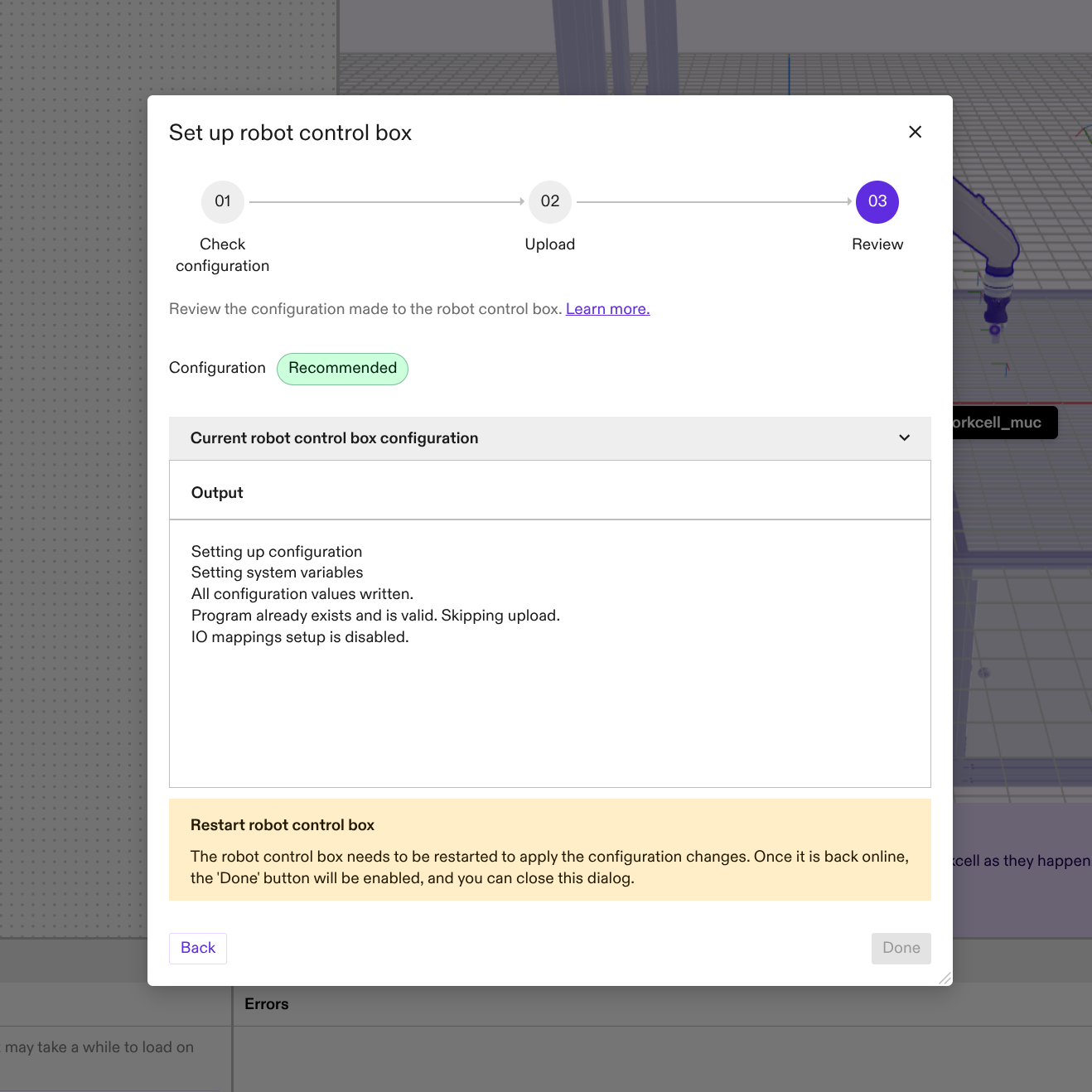
This will open the following setup assistant that will walk you through the setup procedure. Click on the corresponding steps below for more information:
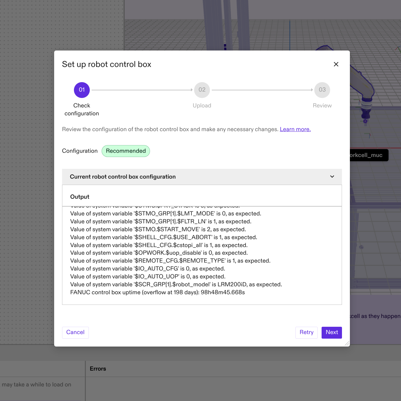
- Step 1: Verification
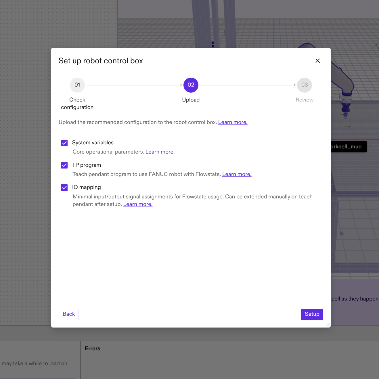
- Step 2: Setup
- Step 3: Review
The first step will display the current configuration of the robot control box listing potential configuration mismatches. The overall configuration state of the robot control box is displayed with a colored label towards the top of the dialog.
In the second step you can select whether to apply all the different configuration options or selectively disable some features of the automated setup and verification process in case they are in conflict with your special robot cell setup.
- System variables: Disables updating the system variables needed for using a FANUC robot with Flowstate. For more details see here.
- TP program: Disables updating the robot Teach Pendant program during the setup process. For more details see here.
- IO mapping: Disables that the IO mappings necessary to control the robot from Flowstate are written via FTP. For more details see here.
In case you will de-select any of the options, please make sure to apply the required settings manually. Refer to the corresponding section for more details.
In the last steps you can review the applied changes. To apply the changes to the FANUC control box, you'll have to restart it. Once the robot has been successfully rebooted, you will be able to close the dialog box.
-
Finally put the FANUC control box into AUTO mode by turning the switch on the control box and turn the teach pendant off by turning the corresponding switch on the teach pendant.
The changes will only active after a reboot of the robot control box.
Now all necessary configuration values have been set on the FANUC control box and the robot can be controlled from Flowstate.
(Optional) FANUC hardware module driver configuration
Additional options can be set in the FANUC hardware module driver configuration. The following section discusses some of these optional settings. For this purpose in Flowstate, select the robot in the 3D scene or the scene tree and then in the left side panel select Config.
Configure the payload index
It is possible to set the payload in Flowstate and on the FANUC control box from
Flowstate using the set payload skill.
By default, this will use the payload index 1. In case a different payload
index on the FANUC control box should be used, adjust the FANUC hardware module
driver configuration as follows:
In Flowstate, select the robot in the 3D scene or the scene tree. In the left
side panel select Settings | Manage configuration.
Edit the file in the text window as highlighted below:
# ...
  module_config {
    [type.googleapis.com/intrinsic_proto.icon.FanucConfig] {
      controller_ip: "192.170.10.1"
      # ...
      payload_update_config: {
        payload_index: 1
      }
    }
  }
# ...
Adjust the teach pendant program on the FANUC teach pendant to use the chosen
index as well in the PAYLOAD[X] statement.
Configure Digital Input and Outputs
The FANUC Stream Motion interface provides access to most digital inputs and
outputs that are also available on the robot (see register_type values below
for possible IO types).
To use the FANUC IOs within Flowstate, you need to adapt the hardware module driver configuration to specify which IOs should be exported to Flowstate.
In Flowstate, select the robot in the 3D scene or the scene tree. In the left side panel select Settings | Manage configuration.
Edit the file in the text window as highlighted in the example below. Below the example, you will find explanations for each configuration field.
    # ...
    [type.googleapis.com/intrinsic_proto.icon.FanucConfig] {
      controller_ip: "192.170.10.1"
      # ...
      input_block_configs: {
        key: "digital_input"
        value: {
          register_type: DIGITAL_INPUT
          index: 1 # This index is one-based.
          mask: 0xFFFF  # All 16 IO starting at DI[1]
        }
      }
      input_block_configs: {
        key: "robot_input"
        value: {
          register_type: ROBOT_INPUT
          index: 1
          mask: 0xFF  # First 8 RI starting at RI[1]
        }
      }
      output_block_configs: {
        key: "digital_output"
        value: {
          register_type: DIGITAL_OUTPUT
          index: 25
          mask: 0xA  # In binary 1010, meaning output 2 and 4 relative to index 25, i.e. DO[26] and DO[28]
        }
      }
    }
    # ...
FANUC allows reading/writing IOs in blocks of up to 16 IOs. You can define multiple IO blocks. The maximum number of blocks is 64, each for inputs and outputs. However, each additional block introduces a processing delay of IOs of one control cycle, i.e. 8ms. This is due to the fact that the FANUC Stream Motion interface allows only to set a single block of outputs and reports only a single block of inputs per control cycle.
-
keyshould describe the block, and this name is used to report the block in Flowstate. It must be unique for input or output blocks. This is also the name that needs to be used in the realtime control service config for the adio part to export the IOs to Flowstate. -
register_typedefines which FANUC register type should be used for a single block. The possible types are:- DIGITAL_INPUT
- DIGITAL_OUTPUT
- ROBOT_INPUT
- ROBOT_OUTPUT
- STANDARD_OPERATOR_PANEL_INPUT
- STANDARD_OPERATOR_PANEL_OUTPUT
- WELD_INPUT
- WELD_OUTPUT
- USER_OPERATOR_PANEL_INPUT
- USER_OPERATOR_PANEL_OUTPUT
- WIRE_SOLDERING_INPUT
- WIRE_SOLDERING_OUTPUT
- FLAG
- MARKER
Consult the FANUC manuals for more information about the different register types.
-
indexis the starting index of a FANUC IO block. This indexing is one-based, whereas Flowstate indices are zero-based. -
maskmasks register values for reading or writing. General information on bit masks can be found on Wikipedia. Based on this mask the IO indices in Flowstate are generated consecutively starting with the least significant bit as index 0. This means gaps in the FANUC IO block are ommitted in the Flowstate indexing. You can see an example of this using the digital outputs in the figure below.- A mask of
0x00would mean all values are ignored (this is invalid). - A mask of
0x01means the first IO is reported/written. In other words, the least significant bit of the bit mask refers to the first IO of the block. - A mask of
0xA(in binary0b1010, notation not supported by protobuf unfortunately) means the second and fourth IO are reported/written. - A mask of
0xFFFFmeans all 16 values are reported to/written from Flowstate.
- A mask of
Add the IO blocks to the realtime control service configuration
To edit the real-time control service configuration in the Flowstate Editor:
- Open the Service tab in the right-side panel.
- Select the real-time control service (default: robot_controller).
- In the left-side panel, choose Config.
- Edit the configuration using one of the following methods:
- Directly in the UI.
- Open the code view via the overflow menu (...) > Open in Dialog > Code.
Add or adjust the ADIO part as follows in the highlighted section:
[type.googleapis.com/intrinsic_proto.icon.IconMainConfig]: {
  # ...
  realtime_control_config: {
    parts_by_name:  {
      key:  "adio"
      value:  {
        part_type_name:  "HalADIOPart"
        config:  {
          [type.googleapis.com/intrinsic_proto.icon.HalADIOPartConfig]:  {
            digital_inputs:  {
              interface:  {
                module_name:  "robot"
                interface_name:  "digital_input"
              }
            }
            digital_inputs:  {
              interface:  {
                module_name:  "robot"
                interface_name:  "robot_input"
              }
            }
            digital_outputs:  {
              interface:  {
                module_name:  "robot"
                interface_name:  "digital_output"
              }
            }
          }
        }
        safety_action_type_name:  "intrinsic.empty"
      }
    }
    # ... other parts
  }
  # ...
}
Each input_block_configs from the hardware module driver configuration must
have a corresponding digital_inputs element in this realtime service
configuration. The same applies to output_block_configs and digital_outputs.
module_namemust match the name of the hardware module driver name as specified above. By default, this isrobot.interface_nameis the value ofkeyininput_block_configs/output_block_configs.
Each of those IO blocks can be addressed in Flowstate via ${module_name}_${interface_name}.
Converting digital FANUC IO blocks to an analog Flowstate IO (optional, for experts)
Even though FANUC Stream Motion does not support analog IOs directly, it is possible to map analog IOs to digital IOs on the FANUC control box with a BG Logic program and interpret the digital IO block in Flowstate as an analog IO. It is also possible to transmit other integer values to Flowstate that can be stored in a register on FANUC side such as encoder ticks. All values need to be scaled and offset to fit into the 16-bit number range offered by FANUC (0-65535).
In the following section, we explain the necessary steps for setting up such analog IOs.
-
Create a FANUC BG logic program on the FANUC control box that maps a 16-bit integer analog IO to a digital IO block similar to the following example program. Refer to the FANUC manuals for instructions on how to run a BG Logic program. FANUC analog IOs are 16-bit, so they can be mapped to a block of 16 DIs for maximum precision. It is also possible to use fewer bits. Flowstate will interpret the received number of bit values as an integer, e.g. if 4 bits are configured on Flowstate side for a IO block the number range of the analog value is [0,15].
Example FANUC BG Logic program for mapping analog input
AI[1]to the digital outputsDO[1-16]:It is not allowed to use backwards jumps or FOR loops in a BG Logic progam. Therefore the loops needs to be unrolled. The
DOstarting index is configure with lineR[2]=1. TheDIcannot be written from the BG Logic program, so we need to go through theDO.noteMake sure that the used registers
R[x]are not used by other teach pendant programs./PROG BG_AI_DO
/ATTR
DEFAULT_GROUP = *,*,*,*,*,*,*,*;
/APPL
/MN
1: ! This example uses AI[1] ;
2: ! Exchange as needed ;
3: R[1]=(AI[1]) ;
4: ! This is the DO start index ;
5: ! Iterates from 1 to 16 ;
6: ! Exchange as needed ;
7: R[2]=1 ;
8: R[3]=R[1] MOD 2 ;
9: DO[R[2]]=R[3] ;
10: R[1]=R[1] DIV 2 ;
11: R[2]=R[2] + 1 ;
12: R[3]=R[1] MOD 2 ;
13: DO[R[2]]=R[3] ;
14: R[1]=R[1] DIV 2 ;
15: R[2]=R[2] + 1 ;
16: R[3]=R[1] MOD 2 ;
17: DO[R[2]]=R[3] ;
18: R[1]=R[1] DIV 2 ;
19: R[2]=R[2] + 1 ;
20: R[3]=R[1] MOD 2 ;
21: DO[R[2]]=R[3] ;
22: R[1]=R[1] DIV 2 ;
23: R[2]=R[2] + 1 ;
24: R[3]=R[1] MOD 2 ;
25: DO[R[2]]=R[3] ;
26: R[1]=R[1] DIV 2 ;
27: R[2]=R[2] + 1 ;
28: R[3]=R[1] MOD 2 ;
29: DO[R[2]]=R[3] ;
30: R[1]=R[1] DIV 2 ;
31: R[2]=R[2] + 1 ;
32: R[3]=R[1] MOD 2 ;
33: DO[R[2]]=R[3] ;
34: R[1]=R[1] DIV 2 ;
35: R[2]=R[2] + 1 ;
36: R[3]=R[1] MOD 2 ;
37: DO[R[2]]=R[3] ;
38: R[1]=R[1] DIV 2 ;
39: R[2]=R[2] + 1 ;
40: R[3]=R[1] MOD 2 ;
41: DO[R[2]]=R[3] ;
42: R[1]=R[1] DIV 2 ;
43: R[2]=R[2] + 1 ;
44: R[3]=R[1] MOD 2 ;
45: DO[R[2]]=R[3] ;
46: R[1]=R[1] DIV 2 ;
47: R[2]=R[2] + 1 ;
48: R[3]=R[1] MOD 2 ;
49: DO[R[2]]=R[3] ;
50: R[1]=R[1] DIV 2 ;
51: R[2]=R[2] + 1 ;
52: R[3]=R[1] MOD 2 ;
53: DO[R[2]]=R[3] ;
54: R[1]=R[1] DIV 2 ;
55: R[2]=R[2] + 1 ;
56: R[3]=R[1] MOD 2 ;
57: DO[R[2]]=R[3] ;
58: R[1]=R[1] DIV 2 ;
59: R[2]=R[2] + 1 ;
60: R[3]=R[1] MOD 2 ;
61: DO[R[2]]=R[3] ;
62: R[1]=R[1] DIV 2 ;
63: R[2]=R[2] + 1 ;
64: R[3]=R[1] MOD 2 ;
65: DO[R[2]]=R[3] ;
/POS
/ENDnoteThere are different options for achieving this on the FANUC control box. This is just an example.
-
Map the chosen range of digital outputs onto digital inputs on the FANUC teach pendant:
MENU -> I/O (5) -> DIGITAL (3). PressCONFIGon the status bar to modify the configuration (XXcan be freely chosen in the range of valid values but need to be the same forDOandDI):- Map DO[1-16] to rack 0, slot 0, start XX
- Map DI[1-16] to rack 0, slot 0, start XX
-
Configure the FANUC hardware module driver in Flowstate to include the analog conversion. Open the configuration UI by navigating in Flowstate to
Services -> $robot -> Config. If theanalog_conversionobject is present in the protobuf configuration file, the digital IO block will be converted to a single analog IO. The maximum precision is an 16 bit integer since one FANUC IO block contains at most 16 bits. But if due to an incomplete mask fewer bits are used, Flowstate will use those bits to convert the bits first to an integer and then to a double value using the scaling and offset factor.The input conversion formula is:
double flowstate_value = read_from_fanuc_controller * scaling_factor + offsetThe output conversion formula is:
uint16 write_to_fanuc_controller = (flowstate_value - offset) / scaling_factorTo convert a digital FANUC IO block to an analog Flowstate IO, just add the
analog_conversionfield to the hardware module driver configuration:[type.googleapis.com/intrinsic_proto.icon.HardwareModuleConfig] {
module_config {
[type.googleapis.com/intrinsic_proto.icon.FanucConfig] {
controller_ip: "192.170.10.1"
# ...
input_block_configs: {
key: "input"
value: {
register_type: DIGITAL_INPUT
index: 1
mask: 65535
analog_conversion: {
scaling_factor: 1.0
offset: 0.0
}
}
}
# ...
}
}
# Add analog input for simulation
simulation_module_config {
additional_devices: {
analog_inputs: {
interface: {
module_name: "robot"
interface_name: "input"
}
}
}
}
# ...
} -
Lastly, use an
analog_inputsblock instead of andigital_inputsblock in the realtime control service in Flowstate (oranalog_outputsinstead ofdigital_outputsfor outputs). Navigate in Flowstate toServices -> $robot_controller -> Config:[type.googleapis.com/intrinsic_proto.icon.IconMainConfig]: {
# ...
realtime_control_config: {
parts_by_name: {
key: "adio"
value: {
part_type_name: "HalADIOPart"
config: {
[type.googleapis.com/intrinsic_proto.icon.HalADIOPartConfig]: {
analog_inputs: {
interface: {
module_name: "robot"
interface_name: "input"
}
}
}
}
safety_action_type_name: "intrinsic.empty"
}
}
# ... other parts
}
# ...
}
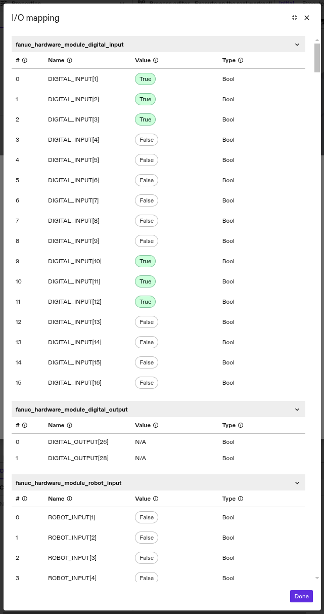
Inspect the IO mapping and IO state in Flowstate
After configuring the FANUC hardware module driver and ICON and enabling control of the robot in the robot control panel, you can inspect whether the mapped IOs represent your intention in Flowstate. To do so, go to File | Equipment Manager in Flowstate. In the Equipment Manager UI, find the realtime control service and select Open I/O status.
- The
I/O mappingdialog shows which IOs are mapped to Flowstate and the current value of the inputs. - The
#column contains the index as used in Flowstate. - The
Namecolumn contains the FANUC register type and index. Check if the desired FANUC IOs are present here.
The image below shows the mapped IO configuration from the example above:
FANUC CRX-specific configuration
The FANUC CRX-series robots are equipped with several collaborative functions, detailed in the "Collaborative Robot Function Operator's Manual" (B-83744EN).
The robot has two distinct modes:
- Collaborative mode: Collaborative safety features are active, and the TCP speed is limited to 1.0 m/s or less. This is indicated by the status LED on the robot base lighting up green.
- High-speed mode: Collaborative features are disabled, and the maximum TCP speed is increased to 2.0 m/s. This mode is activated via a safety input and indicated by a yellow status LED. Flowstate currently only supports this mode.
Flowstate currently only supports the high-speed mode for FANUC CRX robots. The robot control box must be configured accordingly.
To configure the high-speed mode, select "iHMI -> Basic Setup -> CR Setup" from the teach pendant and apply the following settings:
- In
5 Speed Limit Setting, set the speed limit to 1000 mm/s. - In
6 High-Speed Mode SettingselectUse (for Expert User). - In
7 Assign Signal Numberyou will need to assign two digital inputs. These inputs must be persistently set to high (e.g. via an output) when operating the robot with Flowstate:Area 1 Signal Number of SPI: This safety input activates the high-speed mode in which the collaborative features are not available.Area 2 Signal Number of DI: This signal disables the additional velocity limit. If this input is not set to high, the robot will automatically slow down if it exceeds the maximum tip speed defined in5 Speed Limit Setting, as described in section E.2 of the "Stream Motion Operator's Manual" (B-84904EN). This can cause the robot to lag behind its commanded path and accumulate a large tracking error.
After assigning the signals, apply the changes in the DCS parameters and restart the robot control box. For more details and configuration examples refer to "Collaborative Robot Function Operator's Manual" (B-83744EN), section 7.2 "High Speed Mode".
Tips and common issues
Enabling fails with "Robot did not become 'ready' within ..."
Indicates that communication via the Stream Motion interface could not be started.
Use the teach pendant to ensure that the FANUC program is at IBGN start and
in the running state.
Possible explanations:
STEPmode is activated (indicated by an icon on the top left of the teach pendant).
Press theSTEPbutton on the teach pendant to disableSTEPmode.- I/O configuration mismatch.
Double check the robot setup Step 2.
I need to control the FANUC User Inputs (UI) from another external source, e.g. a PLC
It is possible to redirect the IOs that Flowstate controls to a different IO block. This enables the use case that a different control unit should control the FANUC user inputs (UIs) entirely. To use this mode with Flowstate, the external control unit must clear all faults and start the robot program before the clear faults action is triggered in Flowstate—this must be done every time the robot is used.
To enable this mode, set user_input_signals in the hardware module driver
config to a different UI block, e.g. enter value DI[101]. In this example,
Flowstate will control the digital input block starting at DI[101] to
DI[118]. If nothing is connected to this IO block on FANUC control box side,
the control commands from Flowstate such as starting a program will have no
effect, which is intended in this use case. As long as there are no active
faults on the FANUC side and if the teach pendant program is already running,
the hardware module driver will accept this setup.
Enabling fails with "X configuration errors found. Please check the robot control box setup UI for details."
In case there are configuration errors, you will receive the error message "X configuration errors found. Please check the Robot control box setup UI for details". The configuration is checked on the first attempt to enable the service and after every fault. The robot control box setup UI displays the error details. Refer to the FANUC setup section for information on setting up the control box.
Teach pendant or Flowstate reports "SRVO-037 IMSTP input (Group:1)"
This error is expected after a reboot of the FANUC control PC. The digital input
IMSTP needs to be set to ON/true/1 so that FANUC allows robot motions.
To clear this error, trigger "clear faults" from the Flowstate robot control UI
or via the ICON API.
FANUC control box configuration details
This section contains some more information to use a FANUC R30iB control box with Flowstate. The following settings are only relevant in case your specific robot cell settings are incompatible with the automatic setup procedure described above.
The following manual configuration is not necessary when using the automated setup described above.
System variables
On the FANUC teach pendant, access the system variables using
MENU -> --NEXT-- (0) -> System (6) -> Variables (2)
Adjust the followng system variables to the given values
- $STMO.$PHYS_PORT: 2 (Physical network port used for Stream Motion)
- $STMO.$STCM_PRI: 25 (Stream motion task priority)
- $STMO.$STCR_PRI: 25 (Stream motion task priority)
- $STMO.$PKT_STACK: 3 (Maximum number of unprocessed command packets, min 2, max 10)
- $STMO_GRP[1].$LMT_MODE: 0 (Set to 0 means do not use dynamic limits based on current robot pose, which is necessary for Flowstate)
- $STMO_GRP[1].$FLTR_LN:
filter_length(Smoothing factor for destination positions, >1 applies moving average) - $STMO.$START_MOVE: 2 (Number of accumulated command packets before robot starts moving, min 1, max $PKT_STACK-1. This acts as a command buffer compensating for jitter in cycle time.)
- $SHELL_CFG.$USE_ABORT: 1 (UOP CYCLE STOP aborts program at the end of the current cycle if TRUE. This ensure the robot program is fully restarted when Flowstate requests it.)
- $SHELL_CFG.$cstopi_all: 1 (All tasks are aborted when CSTOPI signal is ON if TRUE, otherwise only current task. Necessary to stop lingering tasks, which can prevent starting of the robot program.)
- $OPWORK.$uop_disable: 0 (0 means enable external user input signals so that Flowstate can control the FANUC control box.)
- $REMOTE_CFG.$REMOTE_TYPE: 1 (Enable remote control. Needed so that Flowstate can control the FANUC robot control box.)
- $IO_AUTO_CFG: 0 (Disable automatic assignment of unassigned digital/analog ports at power-up. The FANUC control box should leave the IO assignment as is.)
- $IO_AUTO_UOP: 0 (Turn off auto mapping of user input signals at robot control box power-up. The FANUC control box should leave the IO assignment as is.)
Sensor-based skills will only work properly with lowpass filter length STMO_GRP[1].$FLTR_LN
set to 1.
Teach pendant program
By default the program must be named PNS0003.
The program should look as follows:
1: OVERRIDE=100%
2: PAYLOAD[1:eoat]  # Adapt this here to your payload. When setting payload from Flowstate, index 1 will be used by default.
4: IBGN start[5]
5: IBGN end[5]
IO mapping
The IO mapping for UOPs must be set. The exact starting index is not important.
It is only important that it does not conflict with any other IO mapping.
Navigate to MENU -> I/O (5) -> UOP (7). Press CONFIG on the status bar to
modify the configuration:
- Map UI[1-18] to rack 0, slot 0, start 21
- Map UO[1-20] to rack 0, slot 0, start 1