Plan and execute motions
This page provides an overview of how to use motion skills to plan and execute a
desired motion. The main motion skill that enables the user to define planning
problems, plan, and execute the required motion is the move_robot skill. The
motion can be specified using the parameters of the skill. This document
highlight the different options to set up motion requests through the Flowstate
UI.
Motion Segments
A motion in the move_robot skill is composed of a sequence of
motion segments. A motion segment defines:
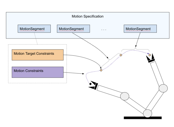
-
A motion target that directly or indirectly defines the final robot configuration for this segment. The target is defined as a set of constraints that can be specified in terms of either joint position or Cartesian constraints like the pose. The motion target is the only required parameter for a motion segment.
-
The motion type defines whether the motion should enforce joint space interpolation, a linear Cartesian motion, or any (i.e., allow arbitrary motions as output by a motion planner). The last option is the default.
-
A set of motion constraints that constrain the motion within this segment. Examples of such motion constraints are collision settings, joint limits, or path constraints.
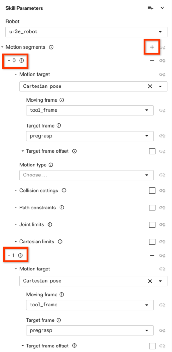
Adding Motion Segments
A motion can be composed of one or more motion segments which can be
specified in the Inputs section of the move_robot skill by clicking on
on the Add repeated element icon next to the Motion segments parameter
in the Skill Parameters section.
When the motion consists of only one segment, the defined motion target defines the final configuration of the robot at the end of the motion.
When multiple motion segments are defined, the motion targets of the non-final segments define waypoints. The resulting trajectory does not stop at these waypoints and only passes these waypoints up to a user-defined blending radius. The motion target of the final segment defines the final motion configuration at which the robot arm comes to a halt.
As soon as one or more motion segments are added, several parameter options are displayed for the user to configure.
A new segment can be added using the + button next to the motion segment field
on top. Each motion segment can be individually designed. Each of these
segments has to define a motion target. All properties concerning the motion
itself, such as Motion type, Collision setting, Path constraints, Cartesian limits and Joint Limits can be
left empty. If any of those are defined, they are only valid for this motion
segment.
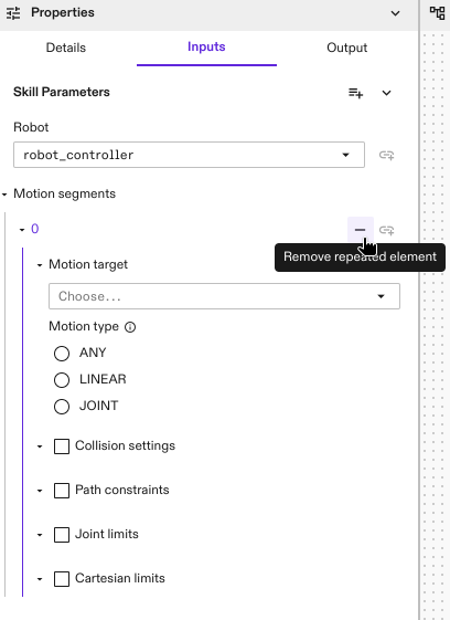
A motion segment can be removed by pressing the - button associated with each of the motion segments.
Each motion segment is indicated with a number under the Motion segment
section. See the highlighted numbers in the graphic at the right side.
The following examples go through defining motions with one or more motion segments while showcasing the different options available. First the options available to configure a motion segment are discussed, followed by general planning and execution parameters for motions with multiple segments.
Motion Targets
The motion targets, or goals, are defined within the individual motion segments. Each motion segment contains one motion target. Each motion target is defined by one or more constraints. A series of waypoints can be defined by specifying a series of motion segments.
The following sections discuss three examples of commonly used motion target constraints: joint configuration, cartesian pose, and an intersection constraint that combines two or more constraints.
Joint Position Targets
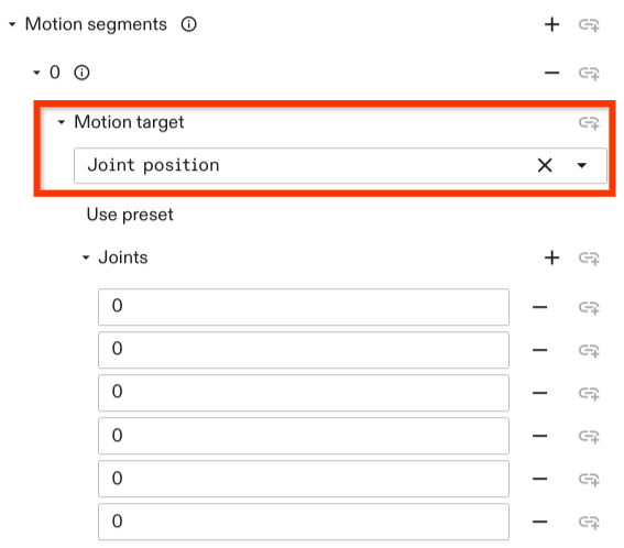
A joint configuration motion target can be set by selecting the Joint position constraint. Upon choosing the constraint you have the option to either use a preset configuration
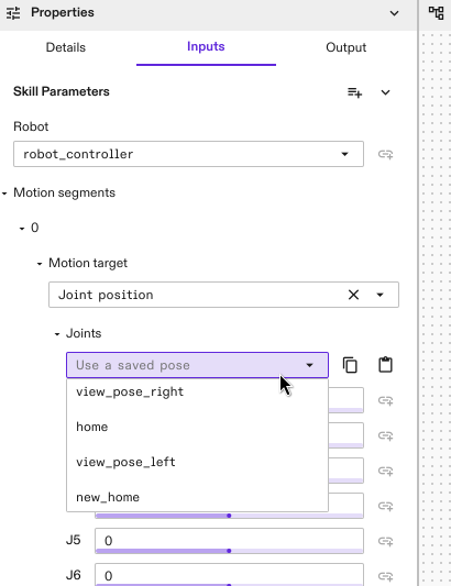
(can be set in the robot pose settings in the robot control panel using Save current pose)
or set the joint positions manually in the fields under Joints which correspond to the order of joints in the kinematic chain.
Cartesian Pose Targets
A Cartesian pose motion target can be set by selecting the option
Cartesian pose in the Motion target drop down menu. The constraint has the
following options to set:
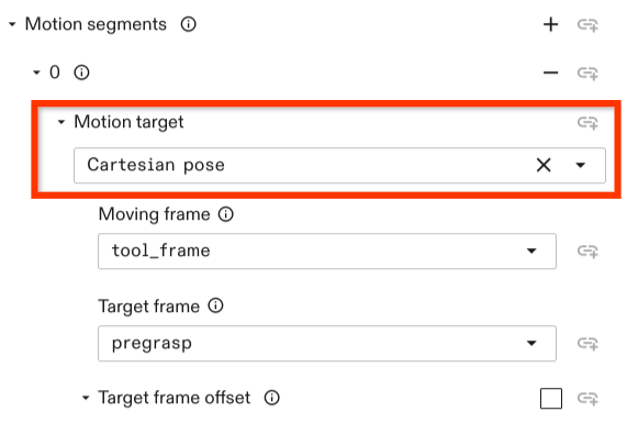
-
Moving frame: Defines the frame that should be moved to a target. The moving frame needs to be attached to the kinematic chain of the robot.
-
Target frame: The frame with which the moving frame should align or should have a relative pose to. Usually, this defines the motion target. A relative offset between the moving frame and the target frame can be defined with the optional
Target frame offsetpose. -
Target frame offset: Defines the desired pose of the moving frame relative to the target frame.
If not set, this defaults to Identity and the
moving framealigns with thetarget frame.
All frame poses referred in the motion target of a motion segment are resolved at the start of that motion segment instead of the whole motion. For example, assuming there are three frames A, B and C with the same pose. In the first motion segment, the motion target is to move frame B by 1 cm in the direction of the +X axes of frame A. In the second motion segment, the motion target is to move frame C by 1 cm in the +X direction of frame B. At the end of both segments, frame C will be at 2 cm in the +X direction of frame A.
Relative Motion Targets
You can also specify motions as relative offsets from the robot's starting
pose. These relative motions can be specified using the
relative_cartesian_pose, relative_position_equality, and
relative_rotation_equality motion targets.
By default, changes in position and /or orientation of the motion are assumed to
be relative to the moving_frame at the start of the motion
segment. Optionally, a reference_frame can be defined instead, which serves as
the reference for relative motion; this enables specifying relative motions that
are independent of the orientation of the moving_frame. For example, this can
be used to implement a motion that moves the tip of the robot by 5cm in the +X
direction of a frame attached to a table.
Combination of Constraints
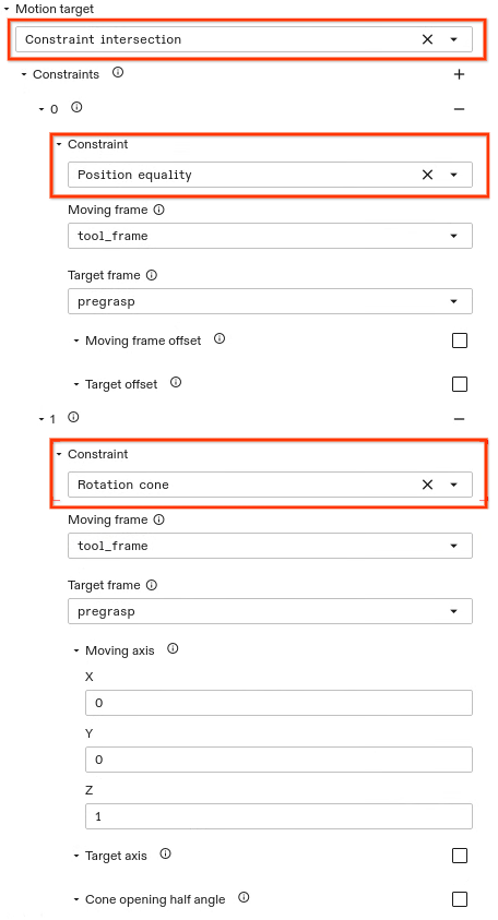
In general, a motion target can be set through a set of different constraints. Constraints can be combined by setting a Constraint intersection. The constraint intersection allows the user to set multiple constraints. A new constraint can be added by clicking on the + button. The motion target is resolved to any joint configuration that satisfies each of the specified constraints.
The example above shows two constraints being set, a point and a rotation
cone constraint. This constraint intersection example results in a robot
configuration such that the position of the tool_frame of the gripper aligns
with the pregrasp frame position. The z axis
of the moving frame (i.e., the gripper tool_frame) aligns with the z
axis of the target frame (i..e., the pregrasp frame) while alignment of the x
axis and y axis are free. The rotation cone constraint allows to set a cone opening half angle. By default, this is set to zero. In this case, the
specified moving frame axis aligns with the specified target frame axis
but is free to rotate around this axis.
Motion Type
In the previous examples, we mostly focused on constraints that affect the motion target, but not the motion in between start and target of a segment. There are three categories of motion allowed here, selected using the motion type parameter:
-
ANY: The default motion type. IfANYor no motion type is specified, a general point to point motion is planned. This involves first checking if a direct (straight-line) connection can be achieved such that all path constraints are satisfied. If not, a valid (e.g., collision free) path is planned. -
JOINT: Using a path planner to find an arbitrary joint-space motion is sometimes not desired. Specifying a motion of typeJOINTallows to prevent path planning. If it is not possible to reach the target with joint space interpolation such that the motion constraints are fulfilled, an error is returned. -
LINEAR: Defines a Cartesian linear motion for the definedmoving frameof the motion target. Linear move segments cannot currently be combined with other motion segments that don't have the same motion type — if one segment is defined asLINEAR, all other segments also need to be specified asLINEAR.
Collision Settings
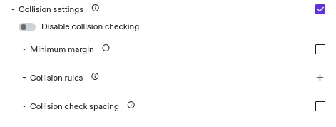
This option allows to define collision settings in the individual motion segments. For example, you could switch collision checking off while retracting from an object and have collision checking active for the remainder of the motion that moves to a specific location. By default, collision checking is always active with a margin of zero.
The collision setting options allow to disable collision checking, set a minimum margin, allow to specify robot-object specific rules, and allow to set the collision checking spacing.
Currently it is not possible for subsequent motion segments of type
LINEAR to set different collision checking properties for each segment in the
motion. If the skill contains multiple subsequent segments of type LINEAR they
all need to set the same collision settings.
Disabling Collision Checking

By default collision checking is activated. To disable collision checking you have to set the corresponding option:
- Enable Collision settings settings by checking the box associated with this field.
- Set the switch to true such that the color is not greyed out anymore.
Setting a Minimum Margin
By default collision checking is activated with a minimum margin of zero meters. That means two objects are considered in collision if their geometries intersect. By setting a higher margin, it is possible to increase the minimum distance for the geometries to be considered collision free.

To specify a different value:
- Enable Collision settings by checking the box associated with this field.
- Enable Minimum margin by checking the box associated with this field.
- Set the margin (in m).
Setting Object Specific Rules
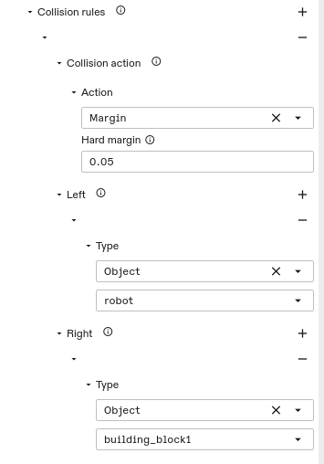
The two previous options, disabling collision checking and setting a minimum margin apply to all object-object pairs. It is also possible to set those rules specific for certain object-object interactions. This can be done by:
- Enable Collision settings by checking the box associated with this field.
- Add a collision rule by clicking the + button.
- Choose the collision action. This could either be a margin or a collision exclusion pair and add the parameters for the action.
- Choose the Left object (e.g. the gripper) by choosing
Objecttype and in the field below choose the first object (e.g., the robot). It is possible to add other objects as well (e.g., an object the robot is holding). - Specify the Right object. If left empty, it applies the rule to all objects specified in left and everything else. Otherwise, only to the left-right object combinations.
Setting Collision Checking Distance
That is the granularity with which the trajectory is checked for collision.
This parameter is optional and is set to 0.01 rad. The parameter only applies
to motions of type LINEAR.
Path Constraints
Path constraints allow to set geometric constraints that apply across the entire segment. For example, they allow to set constraints such that the robot transports an object parallel to the ground (with a rotation cone constraint) or that the motion stays within a certain Cartesian area (with a bounding box constraint).
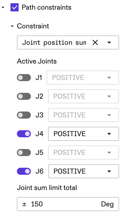
Joint Position Sum Limit Constraint
The Joint Position Sum Limit Constraint allows users to express a path
constraint that involves the summation and/or subtraction of multiple joints,
for example to express the constraint that "the sum of the 4th and the 6th
joints must be no greater than 150 degrees", or mathematically expressed as
|j4 + j6| <= 150. To set this constraint:
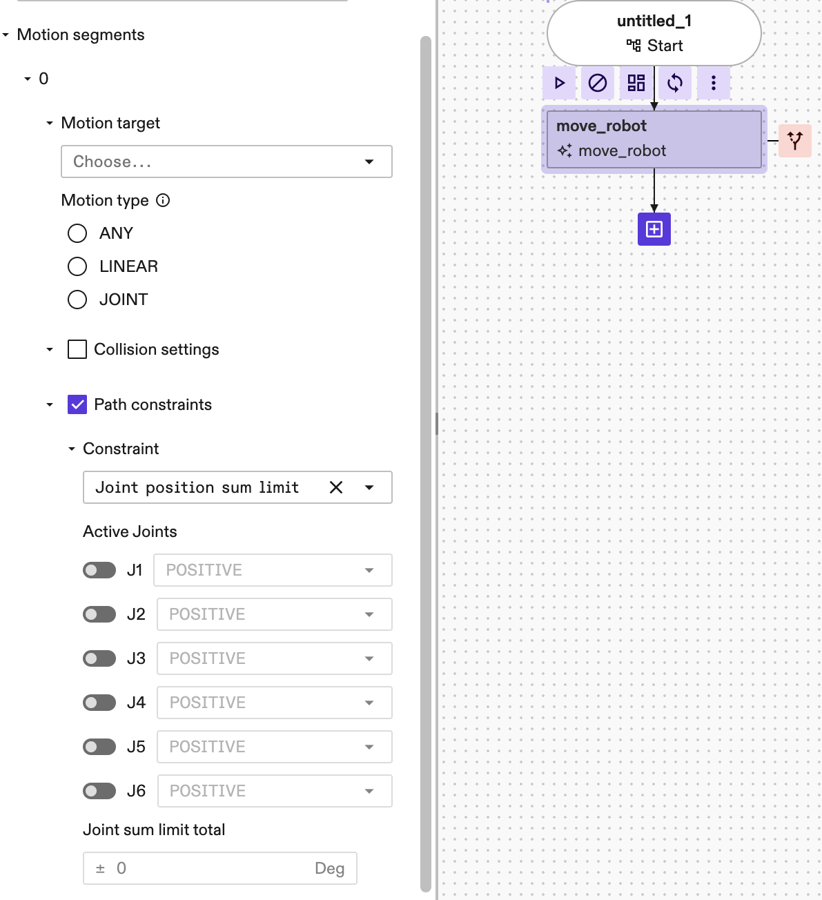
-
Enable Path constraints by checking the box associated with this field.
-
Under the Constraint, select the
Joint position sum limitfrom the dropdown selector. By default, after this constraint is selected, none of the joints are active. -
To activate a joint, for example the 4th joint, click on the corresponding switch to the left of the joint of interest (in this example is the J4 ):
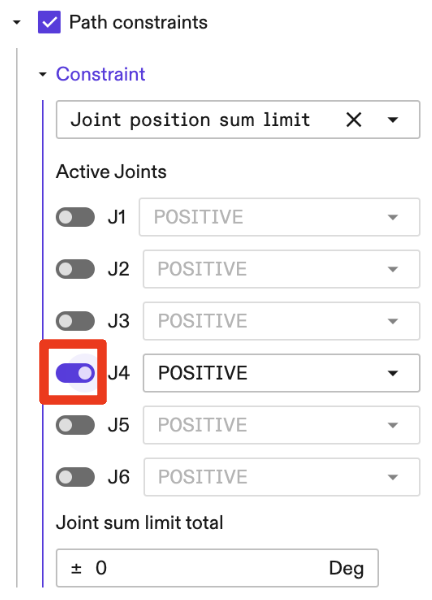
- The following setup represents the constraint
|j4 + j6| <= 150:
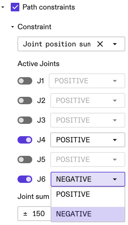
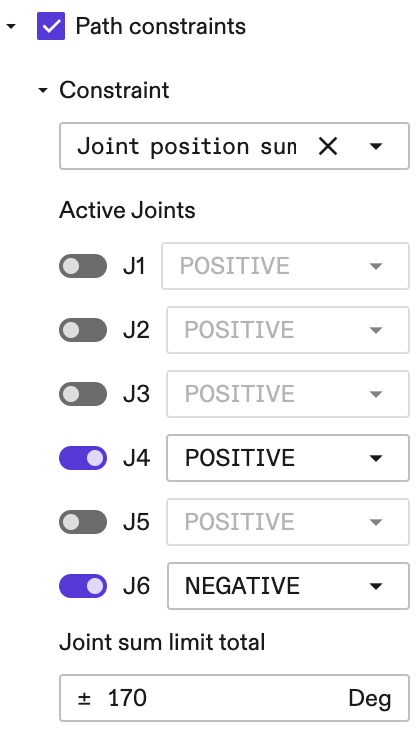
- We can also express a constraint on the subtraction between two joint
positions. For example if we want to have a subtraction constraint
|j4 - j6|then we click on the dropdown selector to the right of J6 as follows:
- The following setup represents the constraint
|j4 - j6| <= 170:
Joint Limits
Joint limits enable to set the joint position, velocity, acceleration and jerk limits of the robot. They apply to the whole motion within the segment including the motion target. To set the joint position limits:
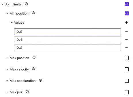
-
Enable Joint limits by checking the box associated with this field.
-
Choose the type of limit you want to set. All limit types that are not set, use the application limits of the robot. However, if one specific limit is checked to be updated, it needs to specify all joint values. For velocity, acceleration, and jerk all limits are symmetric limits. Therefore, only the maximum value is getting specified.
-
Add as many
Valuesfields as the robot has degrees of freedom and enter the limit values. The values are defined in rad, rad/s, rad/s^2, and rad/s^3 respectively. The order of joints corresponds to the order of joints in the kinematic chain.warningThe set limits need to be within the application limits of the robot. If set incorrectly, an error occurs during run time. This error message also lists the application limits the robot adheres to.
warningCurrently, it is necessary to define the same joint limits for each of the segments.
Cartesian Limits
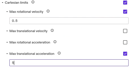
Cartesian limits allow to set the maximum allowed velocity and acceleration of the end-effector in Cartesian space. It is possible to set rotational and translational values. If a limit is not set, the default values configured for the robot are used.
Currently, for motions of type ANY and JOINT we don't apply default
Cartesian limits set for the robot and instead use no limits. Only when the
limits are set in the motion segments they will be applied to the motion of this
segment.
Setting a Blending Parameter
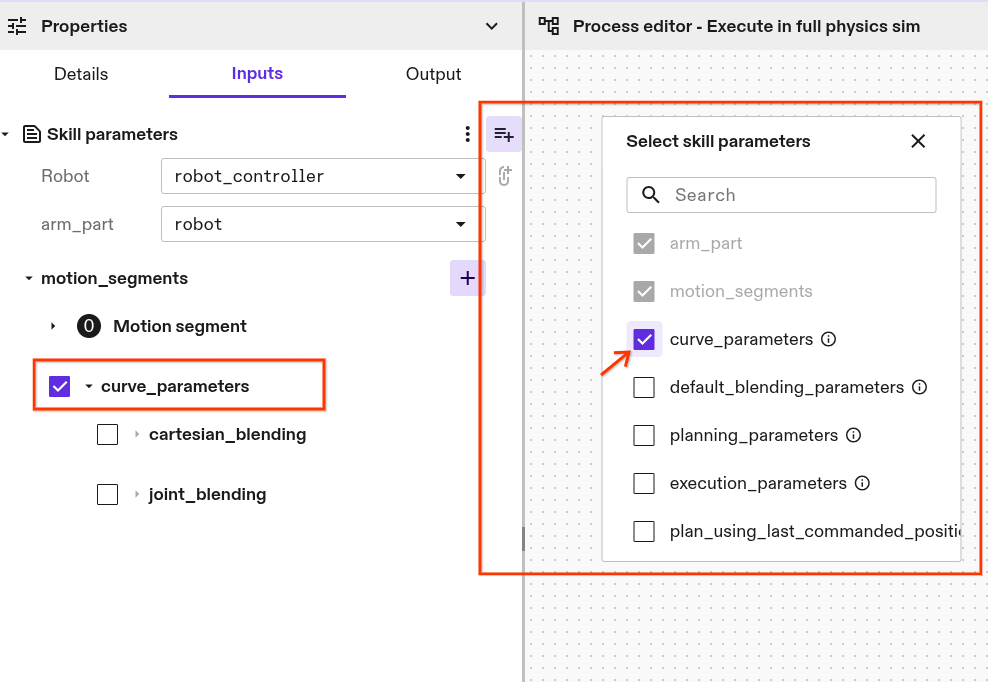 For motion specifications with more than one segment, it is possible to set a
blending parameter that apply to all waypoints.
Depending on the type of motion (i.e., Cartesian or joint space motion), a
different blending parameter type needs to be set. By
default, the blending parameter don't show up in the motion parameter list. To
set them, click the
For motion specifications with more than one segment, it is possible to set a
blending parameter that apply to all waypoints.
Depending on the type of motion (i.e., Cartesian or joint space motion), a
different blending parameter type needs to be set. By
default, the blending parameter don't show up in the motion parameter list. To
set them, click the Manage optional skill parameter button on the upper
right side of the Skill Parameters dialog (see highlight in the picture on the
right). Check Curve parameter and the option shows up below the Motion specification.
Joint Space Blending
We do not recommend using the Joint Space Blending parameter, as it can result in motion adaptions that move the robot arm into collision with its environment. This is particularly problematic in environments with dense object arrangements and small or zero collision margins. If used, keep the blending value as small as possible and add a minimum of 5 cm collision margins to world objects. The exact margin needed will depend on the specific joint blending parameters chosen and cannot be guaranteed.
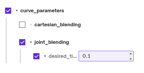
To set the joint blending parameter for blending segments in configuration
space. To set the joint blending parameter, choose the parameter kind
Joint blending. It lets you to set the desired
tightness in rad or degree. It quantifies how closely the blend must pass by the
joint configuration waypoint. It can be interpreted as the coordinate-wise
distance at which the blending arc begins.
Cartesian Space Blending
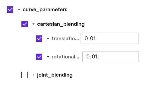
To set the Cartesian blending parameter for Cartesian motions with multiple
motion segments, choose Cartesian blending in the parameter drop down
menu. It allows to set two parameter: Translational corner rounding and
Rotational corner rounding. Each of the parameter is optional. To set them
check the box associated with the parameter.
The Translational corner rounding
defines the Cartesian radius of the circular blend around a Cartesian waypoint
in meter.
The Rotational corner rounding defines the maximum axis angle deviation from
the waypoint in radians.
General Planning Parameters
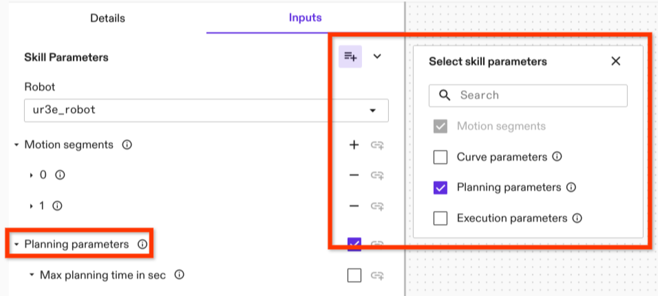 This is an optional parameter. Similar to the blending parameter, it can be
selected in the manage optional skill parameter menu in the upper right corner
of the parameter menu. The planning parameters include:
This is an optional parameter. Similar to the blending parameter, it can be
selected in the manage optional skill parameter menu in the upper right corner
of the parameter menu. The planning parameters include:
max_planning_time_in_sec: defines the maximum time for finding a collision free path in seconds. After this time, the path planner terminates and reports that no valid path can be found. That does not mean that no path exists. Please note that this time limit only applies to the path planner itself. Additional overhead might occur for shortcutting and trajectory generation.path_planner_step_size: a parameter that controls how the motion planner searches for a path. Larger values can lead to faster planning in uncluttered environments; smaller values can lead to faster planning in tightly constrained environments. The default value is0.1.lock_motion_configuration: used for saving and loading motions.skip_fuzzy_cache_check: If true, the motion planner cache will not check for fuzzy matches (see motion planner service cache for details).shortcutting_combine_collinear_segments: if true, the motion planner's internal shortcutting algorithm will save computation time by merging collinear segments; this can result in shorter planning time with slightly longer trajectory durations.
Execution Parameter
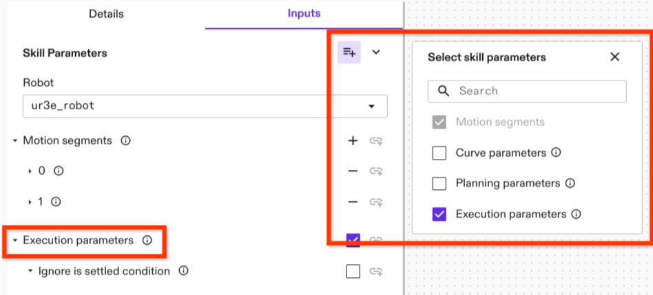 Execution parameters are general parameters that apply to motion execution (as
opposed to planning). There is currently only one execution parameter: the
specification of whether the is settled criterion is used.
Execution parameters are general parameters that apply to motion execution (as
opposed to planning). There is currently only one execution parameter: the
specification of whether the is settled criterion is used.
Is Settled specifies whether or not to use the is settled criterion within the
condition of an Icon action that determines if the motion is completed. The
settling criterion is a dynamic measure that estimates if the robot has settled,
or in other words if its joint velocities are close to zero such that the robot
doesn't move further. Settling requires time, depending on the robot and its
tracking abilities and noise characteristics. Typically it takes between 250 to
750 milliseconds. Be default this parameter is turned on. The option provided as
Execution parameter is Ignore is settled condition which
means that by checking this parameter the is settled criteria is set to false.
Like the previous parameter, the Execution parameter is an optional parameter
that need to be selected in the manage optional skill parameter menu in the
upper right corner of the parameter menu.
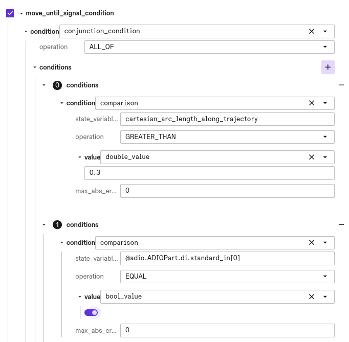
Move Until Signal
Certain processes may require the robot to stop prematurely on its planned
trajectory. This can be implemented by setting the
move_until_signal_parameters appropriately. With these skill parameters you
can define a condition based on ICON part statuses (e.g. DIO states, joint
values) and ICON action state variables (e.g. trajectory progress, time elapsed)
on which to execute a path following stop of the move_robot trajectory.
A skill's trajectory stop condition can be defined in one of two ways: either by
setting a specific digital signal and its expected value, or by utilizing the
more general
ICON Condition
object, which accommodates more complex, user-defined conditions.
The Condition is derived from the action state variables of the executed
trajectory tracking ICON action
and the part statuses configured within the real-time control service.
To create a
condition based on a part status value
the state variable name string encodes a path to the specific value. The
general structure is
@{part_name}.{part_type_node_name}.{field_node_name}[{index}] where the index
is optional for fields that are arrays such as joint values. For a full list of
the available node name strings, refer to the
SDK.
As an example, to access the sensed position of the second joint from a part
named arm, the state variable path would be:
@arm.ArmPart.sensed_position[1]. Furthermore, for any analog or digital IO the
format includes an additional term for the block name:
@{part_name}.{part_type_node_name}.{field_node_name}.{block_name}[{index}].
For example accessing the fourth digital input in a block called standard_in,
the state variable path would be: @adio.ADIOPart.di.standard_in[3].
In the example shown below the robot is conditioned to stop if a digital input is set true and the trajectory has traversed a Cartesian arc-length greater than 0.3 metres.
When the move_robot skill stops due to a triggered condition the
skill return value
stopped_on_signal will be true. This can be used to control behavior tree
logic based on whether themove_robot skill was stopped before its planned end
or not.
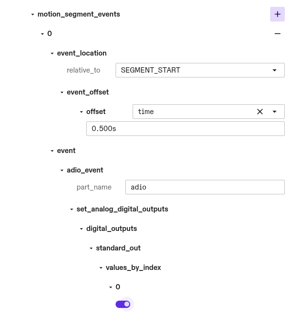
Motion Events
Motion events can be used to trigger events along the robot motion with
real-time accuracy. Motion events are composed of two components, the
event_location which defines where along the robot motion the event will
occur, and the event which defines the effect.
You can define an arbitrary number of motion events for each motion segment with
each having its own event_location and event. Each motion event will trigger
once per execution of the skill.
The location along the trajectory at which an event fires is defined based on an
offset from a reference location on the trajectory. The reference location is
either the start or end of the motion segment the event is part of and can be
defined by setting the relative_to field to SEGMENT_START or
SEGMENT_TARGETrespectively. The motion event is offset by either a time offset
or a Cartesian arc-length distance. The time offset in seconds is absolute and
is not affected by global Speed Override. The cartesian_arc_length_meters is
an offset of the translation distance in meters along the trajectory path. Both
time and cartesian_arc_length_meters offsets can take positive and negative
values. Negative values indicate an event occuring before the reference
location and positive values indicate an event occurring after. Because offset
values can have arbitrary magnitudes, an event_location might be defined to
occur either before the trajectory begins or after its end point. In these cases
the event will be triggered at the boundary of the trajectory. Motion events
scheduled before the trajectory start will trigger during the initial execution
command cycle. Similarly, events scheduled after the final target will trigger
during the final command cycle.
Motion segment blending may cause the robot to bypass start and target positions, as the blended path prioritizes smooth transitions over exact point-to-point accuracy. In this case the reference point is projected onto the center of the blended portion of the trajectory and the Cartesian arc-length and time are calculated relative to this point.
Currently the event which is triggered is limited to writing analog and
digital outputs. These must correspond to valid signals on a configured
HalADIOPart part which is defined in the real-time control service
configuration.